Toyota Tacoma (2015-2018) Service Manual: Disassembly
DISASSEMBLY
CAUTION / NOTICE / HINT
HINT:
- Use the same procedure for both the LH and RH sides.
- The procedure described below is for the LH side.
PROCEDURE
1. REMOVE NO. 1 HEADLIGHT BULB
|
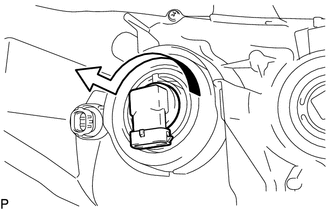
(a) Turn the No. 1 headlight bulb in the direction indicated by the arrow in the illustration to remove it. NOTICE: Do not touch the No. 1 headlight bulb glass. |
|
2. REMOVE NO. 2 HEADLIGHT BULB
|
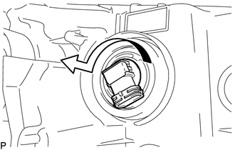
(a) Turn the No. 2 headlight bulb in the direction indicated by the arrow in the illustration to remove it. NOTICE: Do not touch the No. 2 headlight bulb glass. |
|
3. REMOVE FRONT TURN SIGNAL LIGHT BULB
|
(a) Turn the front turn signal light socket with front turn signal light bulb in the direction indicated by the arrow shown in the illustration to remove them. |
|
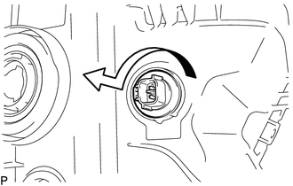
(b) Remove the front turn signal light bulb from the front turn signal light socket.
4. REMOVE CLEARANCE LIGHT BULB
|
(a) Turn the clearance light socket with clearance light bulb in the direction indicated by the arrow shown in the illustration to remove them. |
|
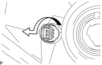
(b) Remove the clearance light bulb from the clearance light socket.
 Components
COMPONENTS
ILLUSTRATION
ILLUSTRATION
...
 Removal
REMOVAL
CAUTION / NOTICE / HINT
HINT:
Use the same procedure for both the LH and RH sides.
The procedure described below is for the LH side.
PROCEDURE
1. REMOVE FRONT BUMPER ASS ...
Other materials:
Removal
REMOVAL
PROCEDURE
1. REMOVE WATER INLET WITH THERMOSTAT SUB-ASSEMBLY
(See page )
2. REMOVE NO. 1 RADIATOR HOSE
3. REMOVE NO. 2 RADIATOR HOSE
4. DISCONNECT RADIATOR RESERVE TANK HOSE
5. SEPARATE TRANSMISSION OIL COOLER HOSE (for Automatic Transmission)
(a) Disengage the c ...
Data List / Active Test
DATA LIST / ACTIVE TEST
1. DATA LIST
NOTICE:
In the table below, the values listed under "Normal Condition" are reference
values. Do not depend solely on these reference values when deciding whether a part
is faulty or not.
HINT:
Using the Techstream to read the Data List allows t ...
Side Turn Signal Light Assembly
Components
COMPONENTS
ILLUSTRATION
Removal
REMOVAL
CAUTION / NOTICE / HINT
HINT:
Use the same procedure for both the RH and LH sides.
The procedure described below is for the LH side.
PROCEDURE
1. REMOVE OUTER REAR VIEW MIRROR ASSEMBLY
(See page )
2. REMOVE OUTER ...
