Toyota Tacoma (2015-2018) Service Manual: Removal
REMOVAL
CAUTION / NOTICE / HINT
HINT:
- Use the same procedure for both the LH and RH sides.
- The procedure described below is for the LH side.
PROCEDURE
1. REMOVE NO. 1 FRONT WHEEL OPENING EXTENSION PAD (w/ Front Spoiler)
.gif)
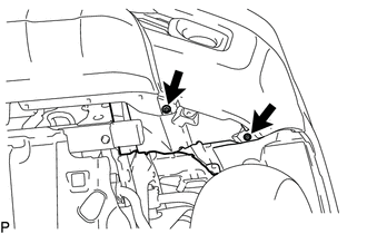
2. SEPARATE FRONT FENDER LINER
|
(a) Remove the 2 screws to separate the front fender liner. |
|
3. REMOVE FOG LIGHT ASSEMBLY
|
(a) Disconnect the connector. |
|
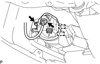
(b) Remove the screw.
(c) Disengage the 2 guides to remove the fog light assembly.
 Disassembly
DISASSEMBLY
CAUTION / NOTICE / HINT
HINT:
Use the same procedure for both the LH and RH sides.
The procedure described below is for the LH side.
PROCEDURE
1. REMOVE FOG LIGHT BU ...
 Adjustment
ADJUSTMENT
PROCEDURE
1. PREPARE VEHICLE FOR FOG LIGHT AIMING ADJUSTMENT
(a) Prepare the vehicle:
HINT:
Ensure that there is no damage or deformation to the body around the
fog lights. ...
Other materials:
Installation
INSTALLATION
PROCEDURE
1. INSTALL NO. 1 FUEL TANK PROTECTOR
(a) Install the No. 1 fuel tank protector to the fuel tank assembly with the
4 clips.
2. INSTALL FUEL SUCTION TUBE SET GASKET
Click here
3. INSTALL FUEL SUCTION TUBE WITH PUMP AND GAUGE ASSEMBLY
Click here
4. INSTALL FUEL PUMP ...
Freeze Frame Data
FREEZE FRAME DATA
1. CHECK FREEZE FRAME DATA
(a) Connect the Techstream to the DLC3.
(b) Turn the ignition switch to ON.
(c) Turn the Techstream on.
(d) Enter the following menus: Body Electrical / Navigation System / Trouble
Codes.
(e) Select a PTC to display its Freeze Frame Data.
2. LIST ...
Floor mat
Use only floor mats designed specifically for vehicles of the same model and
model year as your vehicle. Fix them securely in place onto the carpet.
Insert the retaining hooks (clips) into the floor mat eyelets.
Turn the upper knob of each retaining hook (clip) to secure the floor mats in
...
