Toyota Tacoma (2015-2018) Service Manual: Removal
REMOVAL
CAUTION / NOTICE / HINT
HINT:
- Use the same procedure for the RH side and LH side.
- The following procedure is for the LH side.
PROCEDURE
1. PRECAUTION
NOTICE:
After turning the ignition switch off, waiting time may be required before disconnecting the cable from the negative (-) battery terminal. Therefore, make sure to read the disconnecting the cable from the negative (-) battery terminal notices before proceeding with work.
Click here .gif)
2. DISCONNECT CABLE FROM NEGATIVE BATTERY TERMINAL
NOTICE:
When disconnecting the cable, some systems need to be initialized after the cable is reconnected.
Click here
3. REMOVE REAR DOOR FRAME GARNISH
Click here
4. REMOVE REAR DOOR INSIDE HANDLE BEZEL PLUG
Click here
5. REMOVE REAR DOOR ARMREST BASE UPPER PANEL
Click here
6. REMOVE REAR DOOR TRIM BOARD SUB-ASSEMBLY
Click here
7. REMOVE NO. 1 DOOR TRIM BRACKET
Click here
8. REMOVE REAR DOOR SERVICE HOLE COVER
Click here
9. REMOVE NO. 2 REAR DOOR SERVICE HOLE COVER
Click here
10. REMOVE HOLE PLUG
Click here
11. REMOVE REAR DOOR WINDOW REAR LOWER FRAME SUB-ASSEMBLY
Click here
12. REMOVE REAR DOOR GLASS RUN
Click here
13. REMOVE REAR DOOR GLASS SUB-ASSEMBLY
Click here
14. REMOVE REAR DOOR GLASS OUTER WEATHERSTRIP
|
(a) Put protective tape around the rear door belt moulding assembly. |
|
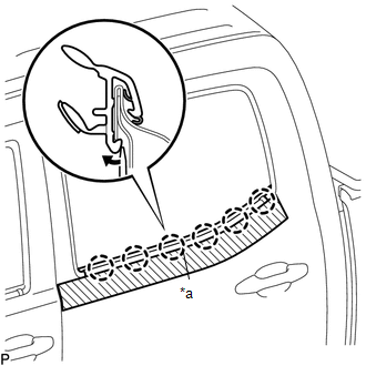
(b) Using a screwdriver, disengage the 6 claws to remove the rear door glass outer weatherstrip.
 Installation
INSTALLATION
CAUTION / NOTICE / HINT
HINT:
Use the same procedure for the RH side and LH side.
The following procedure is for the LH side.
PROCEDURE
1. INSTALL REAR DOOR GLASS O ...
 Rear Door Black Out Tape
Components
COMPONENTS
ILLUSTRATION
Installation
INSTALLATION
CAUTION / NOTICE / HINT
HINT:
Use the same procedure for the RH and LH sides.
The procedure described below is for ...
Other materials:
Certification ECU Communication Stop Mode
DESCRIPTION
Detection Item
Symptom
Trouble Area
Certification ECU Communication Stop Mode
Either condition is met:
Communication stop for "Certification (Smart)" is indicated
on the "Communication Bus Ch ...
On-vehicle Inspection
ON-VEHICLE INSPECTION
PROCEDURE
1. INSPECT PARK/NEUTRAL POSITION SWITCH
(a) Apply the parking brake.
(b) Turn the ignition switch to ON.
(c) Depress the brake pedal and move the shift lever to any position other than
P.
(d) Depress the brake pedal and check that the engine starts when the sh ...
Diagnostic Trouble Code Chart
DIAGNOSTIC TROUBLE CODE CHART
Navigation System
DTC Code
Detection Item
See page
B1324
Lost Communication with Meter
B1532
LVDS Signal Malfunction (from Extension Module)
...
