Toyota Tacoma (2015-2018) Service Manual: Rear Door Black Out Tape
Components
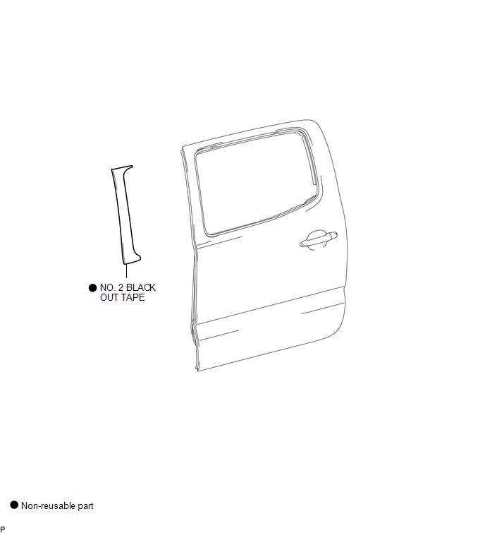
COMPONENTS
ILLUSTRATION
Installation
INSTALLATION
CAUTION / NOTICE / HINT
HINT:
- Use the same procedure for the RH and LH sides.
- The procedure described below is for the LH side.
PROCEDURE
1. REPAIR INSTRUCTION
.gif)
2. INSTALL NO. 2 BLACK OUT TAPE
(a) Refer to the illustration to position a new No. 2 black out tape.
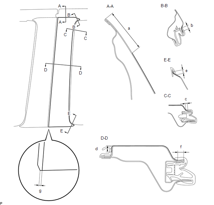 Standard Measurement
|
Dimension |
Measurement |
Dimension |
Measurement |
|---|---|---|---|
|
a |
41.8 mm (1.646 in.) |
b |
7.2 to 7.3 mm (0.283 to 0.2874 in.) |
|
c |
3.8 to 4.0 mm (0.150 to 0.157 in.) |
d |
6.0 to 6.2 mm (0.236 to 0.244 in.) 41.8 mm (** in.) |
|
e |
6.7 to 6.9 mm (0.264 to 0.272 in.) |
f |
5.7 to 5.9 mm (0.224 to 0.232 in.) |
|
g |
2.0 mm (0.0787 in.) |
- |
- |
(b) Remove the release paper and apply the No. 2 black out tape.
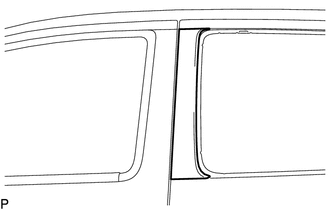
3. INSTALL REAR DOOR GLASS OUTER WEATHERSTRIP ASSEMBLY
(See page
)
Removal
REMOVAL
CAUTION / NOTICE / HINT
HINT:
- Use the same procedure for the RH and LH sides.
- The procedure described below is for the LH side.
PROCEDURE
1. REMOVE REAR DOOR GLASS OUTER WEATHERSTRIP ASSEMBLY
(See page .gif) )
)
2. REMOVE NO. 2 BLACK OUT TAPE
(a) Using a heat light, heat the vehicle body and No. 2 black out tape.
Heating Temperature|
Item |
Temperature |
|---|---|
|
Vehicle Body and No. 2 Black Out Tape |
40 to 60°C (104 to 140°F) |
NOTICE:
Do not heat the vehicle body or No. 2 black out tape excessively.
|
(b) Pull back on one of the ends of the No. 2 black out tape to remove it. HINT: When pulling on the No. 2 black out tape, pull it parallel to the body. |
|
 Removal
REMOVAL
CAUTION / NOTICE / HINT
HINT:
Use the same procedure for the RH side and LH side.
The following procedure is for the LH side.
PROCEDURE
1. PRECAUTION
NOTICE:
After tur ...

Other materials:
Engine does not Start
DESCRIPTION
When the key is in the vehicle and the engine switch is pressed, the certification
ECU (smart key ECU assembly) receives a signal and changes the power source mode.
In addition, when the shift lever is in P or N and the brake pedal is depressed,
the engine can be started by pressi ...
Theft Deterrent System Presence Detection (B279C,B279C95)
DESCRIPTION
If an ECM that is incompatible with the engine immobiliser system is installed,
the ECM stores this DTC.
DTC No.
DTC Detection Condition
Trouble Area
DTC Output Confirmation Operation
B279C*1
An ECM that is incom ...
How To Proceed With Troubleshooting
CAUTION / NOTICE / HINT
HINT:
Use these procedures to troubleshoot the rear view monitor system.
PROCEDURE
1.
VEHICLE BROUGHT TO WORKSHOP
NEXT
2.
CUSTOMER PROBLEM ANALYSIS
...
