Toyota Tacoma (2015-2018) Service Manual: Installation
INSTALLATION
CAUTION / NOTICE / HINT
HINT:
- Use the same procedure for the RH side and LH side.
- The following procedure is for the LH side.
PROCEDURE
1. INSTALL REAR DOOR GLASS OUTER WEATHERSTRIP
|
(a) Engage the 6 claws to install the rear door glass outer weatherstrip. |
|
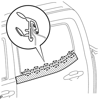
(b) Remove the protective tape.
2. INSTALL REAR DOOR GLASS SUB-ASSEMBLY
Click here .gif)
3. INSTALL REAR DOOR GLASS RUN
Click here
4. INSTALL REAR DOOR WINDOW REAR LOWER FRAME SUB-ASSEMBLY
Click here
5. INSTALL HOLE PLUG
Click here
6. INSTALL NO. 2 REAR DOOR SERVICE HOLE COVER
Click here
7. INSTALL REAR DOOR SERVICE HOLE COVER
Click here
8. INSTALL NO. 1 DOOR TRIM BRACKET
Click here
9. INSTALL REAR DOOR TRIM BOARD SUB-ASSEMBLY
Click here
10. INSTALL REAR DOOR ARMREST BASE UPPER PANEL
Click here
11. INSTALL REAR DOOR INSIDE HANDLE BEZEL PLUG
Click here
12. INSTALL REAR DOOR FRAME GARNISH
Click here
13. CONNECT CABLE TO NEGATIVE BATTERY TERMINAL
Torque:
5.4 N·m {55 kgf·cm, 48 in·lbf}
NOTICE:
When disconnecting the cable, some systems need to be initialized after the cable is reconnected.
Click here
14. INSPECT POWER WINDOW OPERATION
Click here
 Components
COMPONENTS
ILLUSTRATION
ILLUSTRATION
ILLUSTRATION
...
 Removal
REMOVAL
CAUTION / NOTICE / HINT
HINT:
Use the same procedure for the RH side and LH side.
The following procedure is for the LH side.
PROCEDURE
1. PRECAUTION
NOTICE:
After tur ...
Other materials:
Installation
INSTALLATION
CAUTION / NOTICE / HINT
HINT:
Perform "Inspection After Repairs" after replacing the engine assembly, cylinder
head sub-assembly, camshaft, No. 2 camshaft, No. 3 camshaft sub-assembly, No. 4
camshaft sub-assembly, camshaft timing gear assembly, camshaft timing exhaust g ...
Pressure Sensor or Switch (C1254)
DESCRIPTION
The accumulator pressure sensor is connected to the skid control ECU in the master
cylinder solenoid.
DTC No.
DTC Detecting Condition
Trouble Areas
C1254
Accumulator pressure sensor fault
(Fluid pressure does not chang ...
Steering Pad Switch Circuit
DESCRIPTION
The forward recognition camera receives a lane departure alert switch signal
from the steering pad switch assembly.
WIRING DIAGRAM
for 2TR-FE
for 2GR-FKS
CAUTION / NOTICE / HINT
NOTICE:
The vehicle is equipped with a Supplemental Restraint System (SRS) which includes
compo ...
