Toyota Tacoma (2015-2018) Service Manual: Removal
REMOVAL
PROCEDURE
1. REMOVE FRONT FENDER MUDGUARD (w/ Mudguard)
Click here .gif)
2. REMOVE FRONT FENDER WHEEL OPENING MOULDING (w/ Over Fender)
Click here
3. REMOVE FRONT NO. 1 WHEEL OPENING EXTENSION PAD (w/ Front Spoiler)
|
(a) Remove 9 screws and front No. 1 wheel opening extension pad. |
|
4. REMOVE RADIATOR GRILLE
Click here
5. REMOVE FRONT BUMPER ASSEMBLY
(a) w/o Over Fender:
|
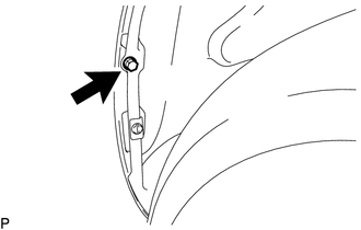
(1) Remove the screw. HINT: Use the same procedure for the RH side and LH side. |
|
|
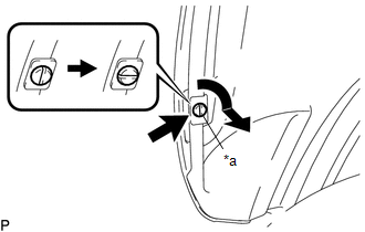
(b) Using a screwdriver, turn the pin 90 degrees and remove the pin hold clip. HINT: Use the same procedure for the RH side and LH side. |
|
|
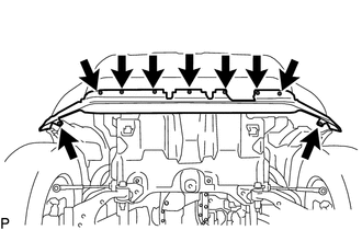
(c) Remove the 4 screws and 2 bolts. |
|
|
(d) Disconnect the connector. |
|
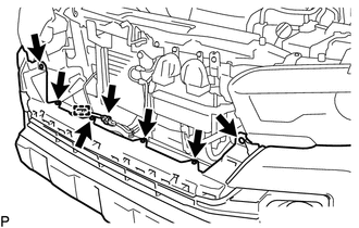
(e) Disengage the clamp.
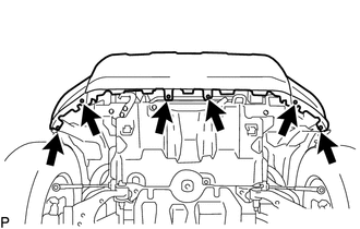
(f) Remove the 6 clips.
|
(g) Put protective tape around the front bumper assembly. |
|
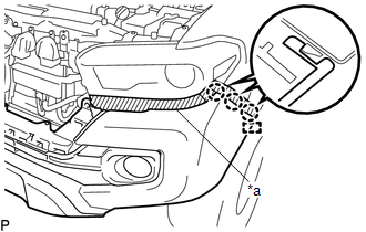
(h) Disengage the guide and 3 claws.
HINT:
Use the same procedure for the RH side and LH side.
(i) w/ Fog Light:
(1) Disconnect the 2 connectors.
(j) Remove the front bumper assembly.
 Reassembly
REASSEMBLY
PROCEDURE
1. INSTALL FRONT BUMPER COVER INSERT LH
(a) Engage the clip to install the front bumper cover insert LH.
(b) Install the b ...
 Installation
INSTALLATION
PROCEDURE
1. INSTALL FRONT BUMPER ASSEMBLY
(a) w/ Fog Light:
(1) Connect the 2 connectors.
(b) Engage the 3 claws and guide to install the front bumper assembly.
(c) Remove the prot ...
Other materials:
Satellite Radio Broadcast cannot be Selected or After Selecting Broadcast, Broadcast
cannot be Added into Memory
CAUTION / NOTICE / HINT
NOTICE:
Some satellite radio broadcasts require payment. A contract must be made between
a satellite radio company and the user. If the contract expires, it will not be
possible to listen to the broadcast.
PROCEDURE
1.
CHECK NAVIGATION RECEIVER ...
Distance Control Switch Circuit
DESCRIPTION
The distance control switch is used to set the distance for vehicle-to-vehicle
distance control mode. The distance control switch is installed in the steering
pad switch assembly. The vehicle-to-vehicle distance set value can be changed by
operating the steering pad switch assembl ...
Terminals Of Ecu
TERMINALS OF ECU
1. CHECK CERTIFICATION ECU (SMART KEY ECU ASSEMBLY)
(a) Disconnect the C27 and C29 certification ECU (smart key ECU assembly) connectors.
(b) Measure the voltage and resistance according to the value(s) in the table
below.
HINT:
Measure the values on the wire harness side w ...
