Toyota Tacoma (2015-2018) Service Manual: Installation
INSTALLATION
PROCEDURE
1. INSTALL FRONT BUMPER ASSEMBLY
(a) w/ Fog Light:
(1) Connect the 2 connectors.
(b) Engage the 3 claws and guide to install the front bumper assembly.
(c) Remove the protective tape.
(d) Install the 6 clips.
(e) Engage the clamp.
(f) Connect the connector.
(g) Install the 2 bolts and 4 screws.
Torque:
Bolt :
5.0 N·m {51 kgf·cm, 44 in·lbf}
Screw :
2.8 N·m {29 kgf·cm, 25 in·lbf}
|
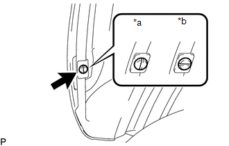
(h) Install the pin hold clip as shown in the illustration. NOTICE: Insert the pin hold clip with the slot aligned vertically. Do not rotate the clip after inserting it. After installation, confirm that the slot is aligned vertically. HINT: Use the same procedure for the RH side and LH side. |
|
(i) w/o Over Fender:
(1) Install the screw.
HINT:
Use the same procedure for the RH side and LH side.
2. INSTALL RADIATOR GRILLE
Click here .gif)
3. INSTALL FRONT NO. 1 WHEEL OPENING EXTENSION PAD (w/ Front Spoiler)
(a) Install front No. 1 wheel opening extension pad with 9 screws.
4. INSTALL FRONT FENDER WHEEL OPENING MOULDING (w/ Over Fender)
Click here
5. INSTALL FRONT FENDER MUDGUARD (w/ Mudguard)
Click here
6. ADJUST MILLIMETER WAVE RADAR SENSOR ASSEMBLY
Click here
 Removal
REMOVAL
PROCEDURE
1. REMOVE FRONT FENDER MUDGUARD (w/ Mudguard)
Click here
2. REMOVE FRONT FENDER WHEEL OPENING MOULDING (w/ Over Fender)
Click here
3. REMOVE FRONT NO. 1 WHEEL OPENING EXTEN ...

Other materials:
Removal
REMOVAL
CAUTION / NOTICE / HINT
HINT:
Use the same procedure for the RH and LH sides.
The procedure described below is for the LH side.
PROCEDURE
1. REMOVE FRONT DOOR GLASS RUN
2. REMOVE FRONT DOOR GLASS OUTER WEATHERSTRIP ASSEMBLY
(See page
)
3. REMOVE NO. 1 BLAC ...
Removal
REMOVAL
CAUTION / NOTICE / HINT
HINT:
Use the same procedure for the RH and LH sides.
The procedure listed below is for the LH side.
PROCEDURE
1. REMOVE REAR DOOR FRAME GARNISH
(See page )
2. REMOVE REAR DOOR INSIDE HANDLE BEZEL PLUG
(See page )
3. REMOVE REAR ARMREST ...
Removal
REMOVAL
PROCEDURE
1. REMOVE INSTRUMENT PANEL SUB-ASSEMBLY
(See page
)
2. REMOVE NO. 3 HEATER TO REGISTER DUCT
3. REMOVE INSTRUMENT PANEL WIRE ASSEMBLY
(a) Using a screwdriver with its tip wrapped in protective tape, release
the 3 airbag connector locks.
Text in Illustr ...
