Toyota Tacoma (2015-2018) Service Manual: Illumination Circuit
DESCRIPTION
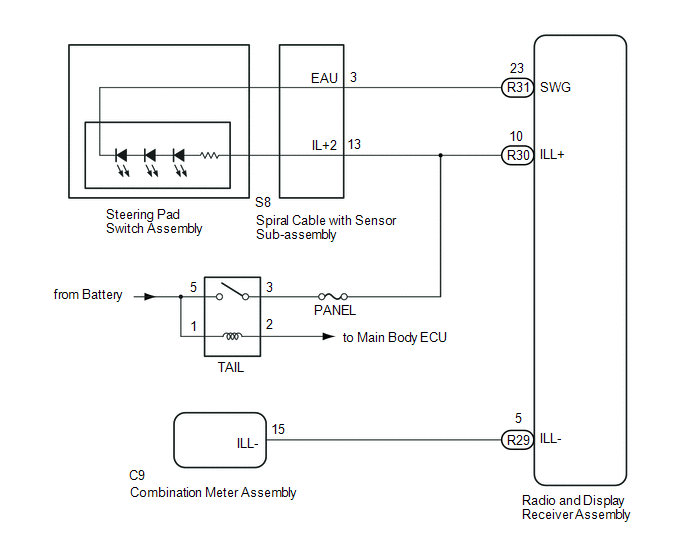
Power is supplied to the radio and display receiver assembly and steering pad switch assembly illumination when the light control switch is in the TAIL or HEAD position.
WIRING DIAGRAM
CAUTION / NOTICE / HINT
NOTICE:
- The vehicle is equipped with a Supplemental Restraint System (SRS) which
includes components such as airbags. Before servicing (including removal
or installation of parts), be sure to read the precautionary notice for
the Supplemental Restraint System (See page
.gif) ).
). - Inspect the fuses for circuits related to this system before performing the following inspection procedure.
PROCEDURE
|
1. |
CHECK ILLUMINATION |
(a) Check if the illumination for the radio and display receiver assembly, steering pad switch, heater control switch or others (hazard switch, transmission control switch, etc.) comes on when the light control switch is turned to the TAIL or HEAD position.
Result|
Result |
Proceed to |
|---|---|
|
Illumination comes on for all components except steering pad switch assembly. |
A |
|
Illumination comes on for all components except radio and display receiver assembly. |
B |
|
Illumination comes on for all components except steering pad switch assembly and radio and display receiver assembly. |
C |
| B | .gif) |
GO TO STEP 6 |
| C | |
GO TO STEP 7 |
|
.gif)
|
2. |
CHECK HARNESS AND CONNECTOR (SPIRAL CABLE WITH SENSOR SUB-ASSEMBLY - BATTERY) |
|
(a) Disconnect the spiral cable with sensor sub-assembly connector. |
|
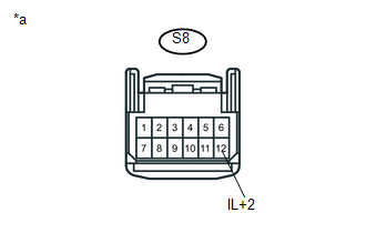
(b) Measure the voltage according to the value(s) in the table below.
Standard Voltage:
|
Tester Connection |
Switch Condition |
Specified Condition |
|---|---|---|
|
S8-13 (IL+2) - Body ground |
Light control switch in the TAIL or HEAD position |
11 to 14 V |
|
*a |
Front view of wire harness connector (to Spiral Cable with Sensor Sub-assembly) |
| NG | |
REPAIR OR REPLACE HARNESS OR CONNECTOR |
|
|
3. |
INSPECT STEERING PAD SWITCH ASSEMBLY |
(a) Remove the steering pad switch assembly (See page
).
(b) Inspect the steering pad switch assembly (See page
).
| NG | |
REPLACE STEERING PAD SWITCH ASSEMBLY |
|
|
4. |
INSPECT SPIRAL CABLE WITH SENSOR SUB-ASSEMBLY |
(a) Remove the spiral cable with sensor sub-assembly (See page
).
(b) Inspect the spiral cable with sensor sub-assembly (See page
).
| NG | |
REPLACE SPIRAL CABLE WITH SENSOR SUB-ASSEMBLY |
|
|
5. |
CHECK HARNESS AND CONNECTOR (SPIRAL CABLE WITH SENSOR SUB-ASSEMBLY - RADIO AND DISPLAY RECEIVER ASSEMBLY AND BODY GROUND) |
(a) Disconnect the S8 spiral cable with sensor sub-assembly connector.
(b) Disconnect the R31 radio and display receiver assembly connector.
(c) Measure the resistance according to the value(s) in the table below.
Standard Resistance:
|
Tester Connection |
Condition |
Specified Condition |
|---|---|---|
|
S8-3 (EAU) - R31-23 (SWG) |
Always |
Below 1 Ω |
|
S8-3 (EAU) - Body ground |
Always |
10 kΩ or higher |
| OK | |
PROCEED TO NEXT SUSPECTED AREA SHOWN IN PROBLEM SYMPTOMS TABLE |
| NG | |
REPAIR OR REPLACE HARNESS OR CONNECTOR |
|
6. |
CHECK HARNESS AND CONNECTOR (RADIO AND DISPLAY RECEIVER ASSEMBLY - BATTERY) |
|
(a) Disconnect the radio and display receiver assembly connector. |
|
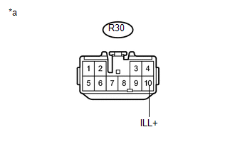
(b) Measure the voltage according to the value(s) in the table below.
Standard Voltage:
|
Tester Connection |
Switch Condition |
Specified Condition |
|---|---|---|
|
R30-10 (ILL+) - Body ground |
Light control switch in the TAIL or HEAD position |
11 to 14 V |
|
*a |
Front view of wire harness connector (to Radio and Display Receiver Assembly) |
| NG | |
REPAIR OR REPLACE HARNESS OR CONNECTOR |
|
|
7. |
CHECK HARNESS AND CONNECTOR (RADIO AND DISPLAY RECEIVER ASSEMBLY - COMBINATION METER ASSEMBLY) |
(a) Disconnect the R29 radio and display receiver assembly connector.
(b) Disconnect the C9 combination meter assembly connector.
(c) Measure the resistance according to the value(s) in the table below.
Standard Resistance:
|
Tester Connection |
Condition |
Specified Condition |
|---|---|---|
|
R29-5 (ILL-) - C9-15 (ILL-) |
Always |
Below 1 Ω |
|
R29-5 (ILL-) - Body ground |
Always |
10 kΩ or higher |
| OK | |
PROCEED TO NEXT SUSPECTED AREA SHOWN IN PROBLEM SYMPTOMS TABLE |
| NG | |
REPAIR OR REPLACE HARNESS OR CONNECTOR |
 Steering Pad Switch Circuit
DESCRIPTION
This circuit sends an operation signal from the steering pad switch assembly
to the radio and display receiver assembly.
If there is an open in the circuit, the audio system cannot be ...
 Parking Brake Switch Circuit
DESCRIPTION
This circuit is from the parking brake switch assembly to the radio and display
receiver assembly.
WIRING DIAGRAM
PROCEDURE
1.
CHECK VEHICLE SIGNAL
...
Other materials:
Blower Motor Controller
Components
COMPONENTS
ILLUSTRATION
Removal
REMOVAL
PROCEDURE
1. REMOVE LOWER NO. 2 INSTRUMENT PANEL AIRBAG ASSEMBLY
(See page )
2. REMOVE INSTRUMENT LOWER PANEL ASSEMBLY
3. REMOVE ECM (for 2TR-FE)
(See page )
4. REMOVE ECM (for 2GR-FKS)
(See page )
5. REMOVE BLOWER MOTOR ...
Heater Circuit (C1AAE)
DESCRIPTION
If the forward recognition camera detects a malfunction in the camera heater
(forward recognition hood) circuit, it will output a malfunction signal to the millimeter
wave radar sensor assembly via CAN communication and DTC C1AAE will be stored.
DTC No.
Detect ...
Inspection
INSPECTION
PROCEDURE
1. INSPECT TIE ROD END SUB-ASSEMBLY
(a) Flip the ball joint stud back and forth 5 times as shown in the illustration
before installing the nut.
(b) Using a torque wrench, turn the nut continuously at a rate of 2 to 4 seconds
per turn and check the torque reading on the ...
