Toyota Tacoma (2015-2018) Service Manual: Short in GPS Antenna (B15C0,B15C1)
DESCRIPTION
These DTCs are stored when a malfunction occurs in the navigation antenna assembly.
|
DTC No. |
DTC Detection Condition |
Trouble Area |
|---|---|---|
|
B15C0 |
Navigation antenna error |
|
|
B15C1 |
Error of the power source to the navigation antenna |
CAUTION / NOTICE / HINT
NOTICE:
Check that the navigation antenna assembly cable is properly installed and does
not have any sharp bends, pinching or loose connections before performing following
inspection procedure (See page .gif) ).
).
PROCEDURE
|
1. |
CHECK DTC |
(a) Clear the DTCs (See page ).
(b) Recheck for DTCs and check that no DTCs are output.
OK:
No DTCs are output.
| OK | .gif) |
USE SIMULATION METHOD TO CHECK |
|
.gif)
|
2. |
INSPECT NAVIGATION ANTENNA ASSEMBLY |
|
(a) Remove the navigation antenna assembly (See page
|
|
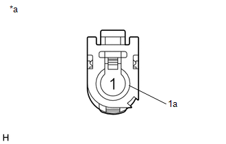
(b) Measure the resistance according to the value(s) in the table below.
Standard Resistance:
|
Tester Connection |
Condition |
Specified Condition |
|---|---|---|
|
1 - 1a |
Always |
50 to 500 Ω |
|
*a |
Component without harness connected (Navigation Antenna Assembly) |
| OK | |
REPLACE NAVIGATION RECEIVER ASSEMBLY |
| NG | |
REPLACE NAVIGATION ANTENNA ASSEMBLY |
 Stereo Component Amplifier Malfunction (B15A3)
DESCRIPTION
This DTC is stored when a malfunction occurs in the stereo component amplifier
assembly.
DTC No.
DTC Detection Condition
Trouble Area
...
 Speed Signal Malfunction (B15C2)
DESCRIPTION
The navigation receiver assembly receives a vehicle speed signal from the combination
meter assembly and information from the navigation antenna assembly, and then adjusts
the vehicle ...
Other materials:
Electrical Key Oscillator(for Rear Floor)
Components
COMPONENTS
ILLUSTRATION
Installation
INSTALLATION
PROCEDURE
1. INSTALL NO. 2 INDOOR ELECTRICAL KEY ANTENNA ASSEMBLY
(a) Engage the clamp to install the No. 2 indoor electrical key antenna assembly.
(b) Connect the connector.
2. INSTALL REAR CONSOLE BOX ASSEMBLY
(See page ...
Diagnosis System
DIAGNOSIS SYSTEM
1. DESCRIPTION
The main body ECU (multiplex network body ECU) and certification ECU (smart key
ECU assembly) control the LIN communication system. LIN communication system data
and Diagnostic Trouble Codes (DTCs) can be read through the Data Link Connector
3 (DLC3).
When th ...
Removal
REMOVAL
PROCEDURE
1. PRECAUTION
NOTICE:
After turning the ignition switch off, waiting time may be required before disconnecting
the cable from the negative (-) battery terminal. Therefore, make sure to read the
disconnecting the cable from the negative (-) battery terminal notices before pr ...
