Toyota Tacoma (2015-2018) Service Manual: Disassembly
DISASSEMBLY
PROCEDURE
1. REMOVE STEERING INTERMEDIATE SHAFT ASSEMBLY
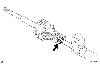
(a) Put matchmarks on the steering intermediate shaft assembly and steering main shaft assembly.
(b) Remove the bolt and steering intermediate shaft assembly.
2. REMOVE UPPER STEERING COLUMN BRACKET WITH SWITCH ASSEMBLY (w/o Smart Key System)
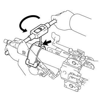
(a) Secure the steering column assembly in a vise between aluminum plates.
NOTICE:
Do not overtighten the vise.
(b) Using a drill, drill a hole in the tapered-head bolt and insert a screw extractor.
(c) Using the screw extractor, remove the tapered-head bolt and upper steering column bracket with switch assembly.
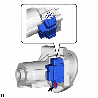
3. REMOVE STEERING LOCK ACTUATOR ASSEMBLY (w/ Smart Key System)
HINT:
Perform the same procedure as for the upper steering column bracket with switch assembly.
4. REMOVE TRANSPONDER KEY AMPLIFIER (w/o Smart Key System)
(a) Disengage the 2 claws to remove the transponder key amplifer.
5. REMOVE IGNITION OR STARTER SWITCH ASSEMBLY (w/o Smart Key System)
(a) Remove the 2 screws and ignition or starter switch assembly from the upper steering column bracket assembly.
6. REMOVE KEY INTER LOCK SOLENOID (for Automatic Transmission without Smart Key System)
(a) Remove the screw.
(b) Disengage the claw to remove the key interlock solenoid from the upper steering column bracket assembly.
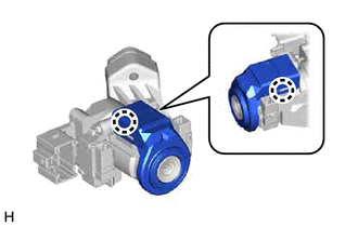
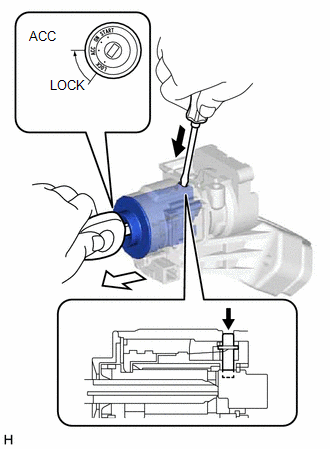
7. REMOVE IGNITION SWITCH LOCK CYLINDER ASSEMBLY (w/o Smart Key System)
(a) Turn the ignition switch to ACC.
(b) Insert the tip of a screwdriver into the hole in the upper steering column bracket assembly, as shown in the illustration, and pull the ignition switch lock cylinder assembly.
 Text in Illustration
.png) |
Push |
.png) |
Pull |
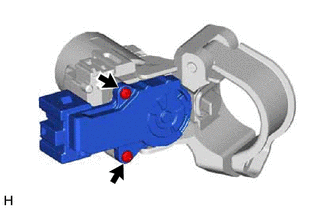
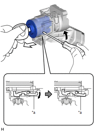
(c) Insert the tip of a screwdriver into the hole in the upper steering column bracket assembly and tilt it upward, as shown in the illustration, to disengage the claw on the ignition switch lock cylinder assembly. Then pull out the ignition switch lock cylinder assembly.
 Text in Illustration
|
*a |
Claw |
|
|
Tilt |
|
|
Pull |
HINT:
When the ignition switch lock cylinder assembly disengages, a click sound is heard.
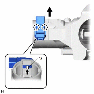
8. REMOVE UN-LOCK WARNING SWITCH ASSEMBLY (w/o Smart Key System)
|
(a) Remove the un-lock warning switch assembly by pushing up the center part and releasing the 2 claws. Text in Illustration
HINT: Slide the un-lock warning switch in the direction shown by the arrow in the illustration to remove it. |
|
 Components
COMPONENTS
ILLUSTRATION
ILLUSTRATION
ILLUSTRATION
ILLUSTRATION
...
 Removal
REMOVAL
CAUTION / NOTICE / HINT
CAUTION:
Some of these service operations affect the SRS. Read the precautionary notices
concerning the SRS before servicing.
Click here
PROCEDURE
1. PRECAUTI ...
Other materials:
Outside Vehicle
General Maintenance
GENERAL MAINTENANCE
CAUTION / NOTICE / HINT
Performing these maintenance checks on the vehicle is the owner's responsibility.
The owner may perform the maintenance or take the vehicle to a service center.
Check the parts of the vehicle described below on a daily basis ...
Parking Brake Switch Circuit
DESCRIPTION
This circuit is from the parking brake switch assembly to the navigation receiver
assembly.
WIRING DIAGRAM
PROCEDURE
1.
CHECK VEHICLE SIGNAL (OPERATION CHECK)
(a) Display the "Vehicle Signal Check Mode" screen (See page
). ...
Data List / Active Test
DATA LIST / ACTIVE TEST
1. DATA LIST
NOTICE:
In the table below, the values listed under "Normal Condition" are reference
values. Do not depend solely on these reference values when deciding whether a part
is faulty or not.
HINT:
Using the Techstream to read the Data List allows t ...
