Toyota Tacoma (2015-2018) Service Manual: Removal
REMOVAL
CAUTION / NOTICE / HINT
CAUTION:
Some of these service operations affect the SRS. Read the precautionary notices concerning the SRS before servicing.
Click here .gif)
PROCEDURE
1. PRECAUTION
NOTICE:
After turning the ignition switch off, waiting time may be required before disconnecting the cable from the negative (-) battery terminal. Therefore, make sure to read the disconnecting the cable from the negative (-) battery terminal notices before proceeding with work.
Click here
2. DISCONNECT CABLE FROM NEGATIVE BATTERY TERMINAL
CAUTION:
Wait at least 90 seconds after disconnecting the cable from the negative (-) battery terminal to disable the SRS system.
NOTICE:
When disconnecting the cable, some systems need to be initialized after the cable is reconnected.
Click here
3. PLACE FRONT WHEELS FACING STRAIGHT AHEAD
4. REMOVE STEERING PAD
Click here
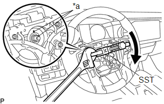
5. REMOVE STEERING WHEEL ASSEMBLY
(a) Remove the steering wheel assembly set nut.
(b) Put matchmarks on the steering wheel assembly and steering main shaft assembly.
|
(c) Using SST, remove the steering wheel assembly. Text in Illustration
SST: 09950-50013 09951-05010 09952-05010 09953-05020 09954-05021 |
|
6. REMOVE LOWER STEERING COLUMN COVER
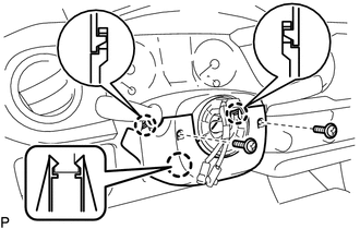
(a) Remove the 2 screws.
(b) Push the right and left sides of the lower steering column cover, and disengage the 2 claws.
(c) Insert a finger into the opening of the tilt lever of the lower steering column cover to disengage the claw and remove the lower steering column cover.
7. REMOVE UPPER STEERING COLUMN COVER
(a) Disengage the claw to remove the upper steering column cover.
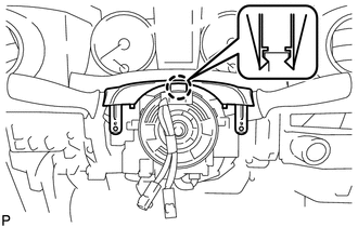
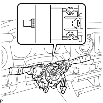
8. REMOVE COMBINATION SWITCH ASSEMBLY WITH SPIRAL CABLE SUB-ASSEMBLY
(a) Disconnect the connectors from the combination switch assembly with spiral cable sub-assembly.
|
(b) Disengage the 3 claws to remove the combination switch assembly with spiral cable sub-assembly from the steering column assembly. |
|
9. REMOVE LOWER NO. 1 INSTRUMENT PANEL AIRBAG ASSEMBLY
Click here
10. REMOVE STEERING COLUMN HOLE COVER
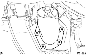
(a) Remove the 4 clips and steering column hole cover.
11. REMOVE NO. 1 ENGINE UNDER COVER SUB-ASSEMBLY
(a) Remove the 4 bolts and No. 1 engine under cover sub-assembly.
12. REMOVE STEERING SLIDING YOKE
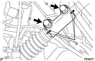
(a) Put matchmarks on the steering sliding yoke, No. 2 steering intermediate shaft and steering intermediate shaft assembly.
Text in Illustration|
*a |
Matchmark |
(b) Remove bolts A and B from the steering sliding yoke.
(c) Slide the steering sliding yoke up and separate it from the No. 2 steering intermediate shaft.
(d) Pull down the steering sliding yoke from the steering intermediate shaft assembly to remove.
13. REMOVE NO. 2 STEERING INTERMEDIATE SHAFT
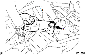
(a) Put matchmarks on the No. 2 steering intermediate shaft and power steering link.
Text in Illustration|
*a |
Matchmark |
(b) Remove bolt C from the No. 2 steering intermediate shaft.
(c) Slide the No. 2 steering intermediate shaft up to remove it from the power steering link.
14. REMOVE STEERING COLUMN ASSEMBLY
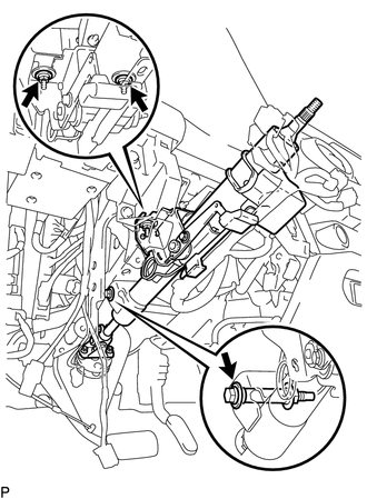
(a) Disconnect the connectors and wire harness clamps.
(b) Remove the bolt, 2 nuts and steering column assembly from the instrument panel reinforcement assembly.
 Disassembly
DISASSEMBLY
PROCEDURE
1. REMOVE STEERING INTERMEDIATE SHAFT ASSEMBLY
(a) Put matchmarks on the steering intermediate shaft assembly and steering main
shaft assembly.
(b) Remove the bolt and st ...
 Installation
INSTALLATION
PROCEDURE
1. INSTALL STEERING COLUMN ASSEMBLY
(a) Install the steering column assembly with the 2 nuts and bolt.
Torque:
21 N·m {214 kgf·cm, 15 ft·lbf}
(b) Connect each of the c ...
Other materials:
System Description
SYSTEM DESCRIPTION
1. ENGINE IMMOBILISER SYSTEM DESCRIPTION
(a) The engine immobiliser system determines whether or not to enable starting
of the SFI system based on a comparison of the key ID code and the vehicle pre-registered
code. The engine immobiliser system compares the vehicle certific ...
Removal
REMOVAL
PROCEDURE
1. REMOVE PROPELLER SHAFT WITH CENTER BEARING ASSEMBLY
(a) Place matchmarks on the propeller shaft flange yoke and differential
flange.
Text in Illustration
*a
Matchmark
...
Installation
INSTALLATION
PROCEDURE
1. INSTALL REAR SEATBACK CENTER HINGE SUB-ASSEMBLY
(a) Install the rear seatback center hinge sub-assembly with the 2 bolts.
Torque:
30 N·m {306 kgf·cm, 22 ft·lbf}
2. INSTALL LUGGAGE COMPARTMENT SIDE TRAY
3. INSTALL REAR SEATBACK HINGE SUB-ASSEMBLY
(a) Install ...
