Toyota Tacoma (2015-2018) Service Manual: Installation
INSTALLATION
PROCEDURE
1. INSTALL STEERING COLUMN ASSEMBLY
(a) Install the steering column assembly with the 2 nuts and bolt.
Torque:
21 N·m {214 kgf·cm, 15 ft·lbf}
(b) Connect each of the connectors to the steering column assembly.
(c) Connect the wire harness clamps to the steering column assembly.
CAUTION:
Wipe any dirt off the installation plane and column body side.
NOTICE:
Be careful not to scratch or soil the installation plane of the steering column.
2. INSTALL NO. 2 STEERING INTERMEDIATE SHAFT
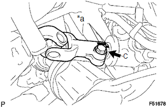
(a) Align the matchmarks on the power steering link and No. 2 steering intermediate shaft.
Text in Illustration|
*a |
Matchmark |
(b) Install the No. 2 steering intermediate shaft to the power steering link with bolt C.
Torque:
35 N·m {357 kgf·cm, 26 ft·lbf}
3. INSTALL STEERING SLIDING YOKE
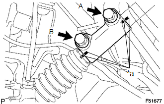
(a) Align the matchmarks on the steering intermediate shaft assembly and steering sliding yoke.
Text in Illustration|
*a |
Matchmarks |
(b) Install the steering sliding yoke to the steering intermediate shaft assembly and slide it upward.
(c) Align the matchmarks on the No. 2 steering intermediate shaft and steering sliding yoke.
(d) Install the steering sliding yoke to the No. 2 steering intermediate shaft with bolts A and B.
Torque:
35 N·m {357 kgf·cm, 26 ft·lbf}
4. INSTALL NO. 1 ENGINE UNDER COVER SUB-ASSEMBLY
(a) Install the No. 1 engine under cover sub-assembly with the 4 bolts.
Torque:
30 N·m {306 kgf·cm, 22 ft·lbf}
5. INSTALL STEERING COLUMN HOLE COVER
(a) Install the steering column hole cover with the 4 clips.
6. INSTALL LOWER NO. 1 INSTRUMENT PANEL AIRBAG ASSEMBLY
Click here .gif)
7. INSTALL COMBINATION SWITCH ASSEMBLY WITH SPIRAL CABLE SUB-ASSEMBLY
(a) Engage the 3 claws to install the combination switch assembly with spiral cable sub-assembly to the steering column assembly.
(b) Connect the connectors to the combination switch assembly with spiral cable sub-assembly.
8. INSTALL UPPER STEERING COLUMN COVER
(a) Engage the claw to install the upper steering column cover.
9. INSTALL LOWER STEERING COLUMN COVER
(a) Engage the 2 claws to install the lower steering column cover.
(b) Install the lower steering column cover with the 2 screws.
(c) Engage the claw.
10. PLACE FRONT WHEELS FACING STRAIGHT AHEAD
11. ADJUST SPIRAL CABLE
Click here
12. INSTALL STEERING WHEEL ASSEMBLY
(a) Align the matchmarks on the steering wheel assembly and steering main shaft assembly.
(b) Install the steering wheel assembly set nut.
Torque:
50 N·m {510 kgf·cm, 37 ft·lbf}
13. INSPECT STEERING WHEEL CENTER POINT
14. INSTALL STEERING PAD
Click here
15. CONNECT CABLE TO NEGATIVE BATTERY TERMINAL
Torque:
5.4 N·m {55 kgf·cm, 48 in·lbf}
NOTICE:
When disconnecting the cable, some systems need to be initialized after the cable is reconnected.
Click here
16. INSPECT SRS WARNING LIGHT
Click here
 Removal
REMOVAL
CAUTION / NOTICE / HINT
CAUTION:
Some of these service operations affect the SRS. Read the precautionary notices
concerning the SRS before servicing.
Click here
PROCEDURE
1. PRECAUTI ...
 Reassembly
REASSEMBLY
PROCEDURE
1. INSTALL UN-LOCK WARNING SWITCH ASSEMBLY (w/o Smart Key System)
(a) Engage the 2 claws to install the un-lock warning switch assembly to the
upper steering column bracket a ...
Other materials:
VSC OFF Indicator Light does not Come ON
DESCRIPTION
Refer to VSC OFF Indicator Light Remains ON (See page
).
WIRING DIAGRAM
Refer to VSC OFF Indicator Light Remains ON (See page
).
CAUTION / NOTICE / HINT
NOTICE:
When replacing the skid control ECU (master cylinder solenoid), perform
calibration (See page
).
...
Inspection
INSPECTION
PROCEDURE
1. INSPECT FRONT SEAT INNER BELT ASSEMBLY LH
(a) Check the resistance.
(1) Measure the resistance according to the value(s) in the table below.
Standard resistance:
Tester Connection
Condition
Specified C ...
Inspection
INSPECTION
PROCEDURE
1. INSPECT FRONT OIL PUMP BODY SUB-ASSEMBLY
(a) Using a dial indicator, measure the inside diameter of the front
oil pump body sub-assembly bushing.
Maximum inside diameter:
38.138 mm (1.50 in.)
If the inside diameter is more than the maximum inside d ...
