Toyota Tacoma (2015-2018) Service Manual: Key Cannot be Registered
DESCRIPTION
A maximum of 5 master key ID codes can be registered.
WIRING DIAGRAM
Refer to "B2780" (See page .gif) )
)
CAUTION / NOTICE / HINT
NOTICE:
If the transponder key ECU assembly is replaced, refer to Registration (See page
).
PROCEDURE
|
1. |
CHECK REGISTRATION MODE |
(a) Check that the system enters registration mode (See page
).
OK:
System enters registration mode.
| NG | .gif) |
GO TO STEP 5 |
|
.gif)
|
2. |
CHECK SECURITY INDICATOR LIGHT OPERATION |
(a) In registration mode, insert the key into the ignition key cylinder and check the security indicator light.
HINT:
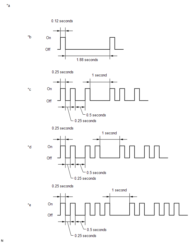
If the new key ID code registration fails, code 2-1 will be output through the security light. Trying to re-register an already registered key will cause code 2-2 to be output when the key is inserted. If the number of registered key ID codes exceeds the maximum limit, code 2-3 will be output through the security indicator light. The output details are shown in the following illustration.
|
*a |
Security Indicator Light |
*b |
Normal (Immobiliser system is operating normally) |
|
*c |
Code 2-1 |
*d |
Code 2-2 |
|
*e |
Code 2-3 |
- |
- |
|
Result |
Proceed to |
|---|---|
|
Code 2-2 is output |
A |
|
Code 2-1 or Code 2-3 is output |
B |
| A | |
END (REGISTERED KEY WAS USED) |
|
|
3. |
READ VALUE USING TECHSTREAM (TRANSPONDER S-CODE, TRANSPONDER M-CODE) |
(a) Connect the Techstream to the DLC3.
(b) Turn the ignition switch to ON.
(c) Turn the Techstream on.
(d) Enter the following menus: Body Electrical / Immobiliser / Data List.
(e) Read the Data List according to the display on the Techstream.
Immobiliser|
Tester Display |
Measurement Item/Range |
Normal Condition |
Diagnostic Note |
|---|---|---|---|
|
Transponder S-code |
Number of registered sub- keys/min. 0, max. 15 |
Number of registered sub-keys |
- |
|
Transponder M-code |
Number of registered master keys/min. 0, max. 15 |
Number of registered master keys |
- |
|
Result |
Proceed to |
|---|---|
|
Values are other than above |
A |
|
0 is displayed for "Transponder M-code" and 3 is displayed for "Transponder S-code" |
B |
|
5 is displayed for "Transponder M-code" and 3 is displayed for "Transponder S-code" |
C |
| B | |
KEY REGISTRATION (MASTER KEY) |
| C | |
MAXIMUM NUMBER OF KEYS ALREADY REGISTERED |
|
|
4. |
KEY REGISTRATION |
(a) Refer to the table below to determine if additional Keys can be registered.
|
Number of Door control transmitter assemblies Registered Master |
Proceed to |
|---|---|
|
0 |
New key ID code registration |
|
1 to 7 |
Additional key ID code registration |
(b) Check if an additional key can be registered.
OK:
Additional key can be registered.
| OK | |
END (KEY MALFUNCTION) |
| NG | |
REPLACE TRANSPONDER KEY ECU ASSEMBLY |
|
5. |
INSPECT UNLOCK WARNING SWITCH ASSEMBLY |
(a) Remove the unlock warning switch assembly (See page
).
(b) Inspection the unlock warning switch assembly (See page
).
| NG | |
REPLACE UNLOCK WARNING SWITCH ASSEMBLY |
|
|
6. |
CHECK HARNESS AND CONNECTOR (TRANSPONDER KEY ECU ASSEMBLY - UNLOCK WARNING SWITCH ASSEMBLY - BODY GROUND) |
(a) Disconnect the T10 transponder key ECU assembly connector.
(b) Disconnect the U1 unlock warning switch assembly connector.
(c) Measure the resistance according to the value(s) in the table below.
Standard Resistance:
|
Tester Connection |
Condition |
Specified Condition |
|---|---|---|
|
T10-3 (KSW) - U1-1 |
Always |
Below 1 Ω |
|
T10-3 (KSW) or U1-1 - Body ground |
Always |
10 kΩ or higher |
|
U1-2 - Body ground |
Always |
Below 1 Ω |
| OK | |
REPLACE TRANSPONDER KEY ECU ASSEMBLY |
| NG | |
REPAIR OR REPLACE HARNESS OR CONNECTOR |
 Engine does not Start but Initial Combustion Occurs
DESCRIPTION
If the key ID codes of the key and transponder key ECU assembly match, the engine
immobiliser system is unset and the engine start permission signal is sent to the
ECM. When the ID co ...
 Security Indicator Light Does not Blink
DESCRIPTION
The transponder key ECU assembly blinks the security indicator light
when the immobiliser is set (no key is in the ignition key cylinder).
w/ Theft Deterrent System:
...
Other materials:
If the vehicle becomes stuck
Carry out the following procedures if the tires spin or the vehicle becomes
stuck in mud, dirt, or snow.
Stop the engine. Set the parking
brake and put the shift lever in P (vehicles with an automatic transmission) or
N (vehicles with a manual transmission).
Remove the mud, snow, or sand f ...
SM Solenoid Circuit (C1225-C1228,C1468,C1469,C146A,C146B)
DESCRIPTION
The solenoid goes on when signals are received from the skid control ECU (master
cylinder solenoid) and controls the pressure action on the wheel cylinders thus
controlling the braking force.
DTC No.
DTC Detecting Conditions
Trouble Areas
...
Installation
INSTALLATION
PROCEDURE
1. INSTALL TRANSFER POSITION SWITCH
(a) Attach the 2 claws to install the transfer position switch.
2. INSTALL AIR CONDITIONING CONTROL ASSEMBLY (for Automatic Air Conditioning
System)
(See page )
3. INSTALL INTEGRATION PANEL SUB-ASSEMBLY (for Manual Cooler System)
...
