Toyota Tacoma (2015-2018) Service Manual: Transmission Fluid Temperature Sensor "B" Circuit Short to Ground (P274011)
DESCRIPTION
The No. 2 ATF temperature sensor is installed in the transmission valve body assembly.
If the ECM detects an abnormally high ATF temperature near this sensor, it illuminates the warning indicator.
HINT:
- The temperature of ATF easily rises when towing, climbing hills, in traffic, etc.
- If the No. 2 ATF temperature sensor becomes short-circuited, the signal that indicates that the ATF temperature is 150°C (302°F) or higher is input into the ECM.
Vehicle conditions when the sensor is normal and when the sensor is short-circuited are indicated in the table below.
|
No. 2 ATF Temperature Sensor State |
Detection Condition |
Symptom |
Recovery Condition |
|---|---|---|---|
|
Sensor is normal |
ATF temperature higher than 150°C (302°F) |
ATF temperature warning indicator remains on |
ATF temperature below 135°C (275°F)*1 |
|
ATF temperature higher than 130°C (266°F) |
Shift point too high |
ATF temperature below 110°C (230°F) |
|
|
Sensor is short-circuited |
Any conditions |
Shift point too high |
Symptoms still occur |
|
Engine coolant temperature higher than 95°C (203°F) |
Lock-up at 3rd gear*2 |
Symptoms still occur |
HINT:
*1: When ATF temperature is in the normal range, it decreases to below 135°C (275°F) within 5 minutes with the shift lever in P or N in an idling state.
*2: When ATF temperature is normal, transmission lock-up occurs in 4th, 5th and 6th gear with the shift lever in D or with the S6 range selected, in 4th or 5th gear with the S5 range selected, and 4th gear with the S4 range selected.
|
DTC Code |
DTC Detection Condition |
Trouble Area |
SAE |
|---|---|---|---|
|
P274011 |
The output voltage from the No. 2 ATF temperature sensor is below 0.0459 V for 0.5 seconds or more (1 trip detection logic). |
|
P2742 |
MONITOR DESCRIPTION
The No. 2 ATF temperature sensor converts the ATF temperature to an electrical resistance value. Based on the resistance, the ECM determines the ATF temperature and detects a short in the No. 2 ATF temperature sensor circuit. If the resistance value of the No. 2 ATF temperature sensor is below 25 Ω*, the ECM interprets this as a fault in the No. 2 ATF temperature sensor or wiring. The ECM stores the DTC.
*: 150°C (302°F) or higher is indicated regardless of the actual ATF temperature.
HINT:
The ATF temperature can be checked on the Techstream display.
WIRING DIAGRAM
Refer to DTC P071011 (See page .gif) ).
).
CAUTION / NOTICE / HINT
NOTICE:
- Perform the universal trip to clear permanent DTCs (See page
).
- Perform registration and/or initialization when parts related to the
automatic transmission are replaced (See page
).
HINT:
After the repair, clear the DTCs and perform the following procedure to check that DTCs are not output.
- Start the engine and wait for 3 seconds or more.
- Check for DTCs again (See page ).
1. DATA LIST
HINT:
Using the Techstream to read the Data List allows the values or states of switches, sensors, actuators and other items to be read without removing any parts. This non-intrusive inspection can be very useful because intermittent conditions or signals may be discovered before parts or wiring is disturbed. Reading the Data List information early in troubleshooting is one way to save diagnostic time.
NOTICE:
In the table below, the values listed under "Normal Condition" are reference values. Do not depend solely on these reference values when deciding whether a part is faulty or not.
(a) Warm up the engine.
(b) Turn the ignition switch off.
(c) Connect the Techstream to the DLC3.
(d) Turn the ignition switch to ON.
(e) Turn the Techstream on.
(f) Enter the following menus: Powertrain / Transmission / Data List.
(g) According to the display on the Techstream, read the Data List.
Transmission|
Tester Display |
Measurement Item/Range |
Normal Condition |
Diagnostic Note |
|---|---|---|---|
|
A/T Oil Temperature No. 2 |
No. 2 ATF temperature sensor value/ Min.: -40°C (-40°F) Max.: 150°C (302°F) |
|
If the value -40°C (-40°F) or 150°C (302°F), No. 2 ATF temperature sensor circuit is open or shorted. |
HINT:
- When DTC P274011 is output and the Techstream indicates 150°C (302°F) or higher, there is a short circuit.
- When DTC P274015 is output and the Techstream indicates -40°C (-40°F),
there is an open circuit.
Check the temperature displayed on the Techstream in order to check if a malfunction exists.
|
Temperature Displayed |
Malfunction |
|---|---|
|
-40°C (-40°F) |
Open circuit |
|
150°C (302°F) or higher |
Short circuit |
PROCEDURE
|
1. |
INSPECT NO. 2 ATF TEMPERATURE SENSOR (TRANSMISSION WIRE) |
|
(a) Disconnect the E1 transmission wire connector. |
|
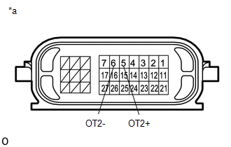
(b) Measure the resistance according to the value(s) in the table below.
Standard Resistance:
|
Tester Connection |
Condition |
Specified Condition |
|---|---|---|
|
5 (OT2+) - 6 (OT2-) |
Always |
25 Ω to 156 kΩ |
|
5 (OT2+) - Body ground |
Always |
10 kΩ or higher |
|
6 (OT2-) - Body ground |
Always |
10 kΩ or higher |
HINT:
If the resistance is out of the specified range at any of the ATF temperatures shown in the table below, the driveability of the vehicle may decrease.
|
ATF Temperature |
Specified Condition |
|
10°C (50°F) |
5 to 8 kΩ |
|
25°C (77°F) |
2.5 to 4.5 kΩ |
|
110°C (230°F) |
0.22 to 0.28 kΩ |
|
*a |
Component without harness connected (Transmission Wire) |
| NG | .gif) |
REPLACE NO. 2 ATF TEMPERATURE SENSOR (TRANSMISSION WIRE) |
|
.gif)
|
2. |
CHECK HARNESS AND CONNECTOR (TRANSMISSION WIRE - ECM) |
|
(a) Disconnect the ECM connectors. |
|
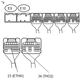
(b) Measure the resistance according to the value(s) in the table below.
Standard Resistance:
|
Tester Connection |
Condition |
Specified Condition |
|---|---|---|
|
E10-34 (THO2) - E9-23 (ETHW) |
Always |
25 Ω to 156 kΩ |
|
E10-34 (THO2) - Body ground |
Always |
10 kΩ or higher |
|
*a |
Rear view of wire harness connector (to ECM) |
| OK | |
REPLACE ECM |
| NG | |
REPAIR OR REPLACE HARNESS OR CONNECTOR |
 Torque Converter Clutch Circuit Short to Battery or Open (P074015)
DESCRIPTION
Shift solenoid valve SL is turned on and off by signals from the ECM to control
the hydraulic pressure acting on the lock-up relay valve, which then controls operation
of the lock-up ...
 Transmission Fluid Temperature Sensor "B" Circuit Short to Battery or Open (P274015)
DESCRIPTION
The No. 2 ATF temperature sensor is installed in the transmission valve body
assembly.
If the ECM detects an abnormally high ATF temperature near this sensor, it illuminates
the warn ...
Other materials:
Problem Symptoms Table
PROBLEM SYMPTOMS TABLE
NOTICE:
Before replacing the ECM, refer to Registration.
w/o Smart Key System: Click here
w/ Smart Key System: Click here
When the millimeter wave radar sensor assembly is replaced with a new
one, adjustment of the radar sensor beam axis must be ...
Software Incompatibility with Body Control Module "B" (U1331)
DESCRIPTION
This DTC is stored when the destination information of the main body ECU (multiplex
network body ECU) does not match that of the blind spot monitor sensors.
DTC Code
DTC Detection Condition
Trouble Area
U1331
Destination in ...
USB Media Malfunction (B1585)
DESCRIPTION
This DTC is stored when a malfunction occurs in a connected device.
DTC No.
DTC Detection Condition
Trouble Area
B1585
USB Device Malfunction
Non mass-storage class or incompatible protocol USB device
...
