Toyota Tacoma (2015-2018) Service Manual: Removal
REMOVAL
PROCEDURE
1. REMOVE FRONT NO. 2 EXHAUST PIPE ASSEMBLY (for 2GR-FKS)
.gif)
2. REMOVE PROPELLER SHAFT HEAT INSULATOR BRACKET SUB-ASSEMBLY
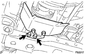
(a) Remove the 2 bolts and propeller shaft heat insulator bracket.
3. REMOVE FRONT PROPELLER SHAFT ASSEMBLY
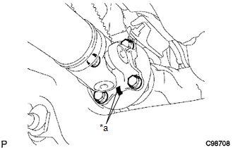
(a) Place matchmarks on the propeller shaft flange and differential flange.
Text in Illustration|
*a |
Matchmark |
(b) Remove the 4 nuts, 4 bolts, 4 washers and front propeller shaft.
|
(c) Place matchmarks on the propeller shaft flange and transfer flange. Text in Illustration
|
|
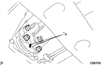
(d) Remove the 4 nuts, 4 washers and front propeller shaft.
 Components
COMPONENTS
ILLUSTRATION
...
 Disassembly
DISASSEMBLY
PROCEDURE
1. INSPECT FRONT PROPELLER SHAFT UNIVERSAL JOINT SPIDER BEARING
(a) Check the spider bearings for wear and damage.
(b) Check each spider bearing's axial play by turning t ...
Other materials:
Stop Light Switch
Components
COMPONENTS
ILLUSTRATION
Inspection
INSPECTION
PROCEDURE
1. INSPECT STOP LIGHT SWITCH
(a) Check the resistance.
(1) Measure the resistance using an ohmmeter, and check the results in accordance
with the value(s) in the table below.
Standard:
Tester Connectio ...
Diagnosis System
DIAGNOSIS SYSTEM
DIAGNOSIS FUNCTION
(a) The diagnosis function turns off the cruise control indicator, illuminates
the master warning light and displays a warning message when a malfunction is detected.
When a malfunction is detected in the dynamic radar cruise control system, DTCs
are store ...
Inspection
INSPECTION
PROCEDURE
1. INSPECT REAR SPEAKER ASSEMBLY (w/o Amplifier Box Speaker Assembly)
(a) Measure the resistance according to the value(s) in the table below.
Standard resistance:
Tester Connection
Condition
Specified Condition
1 - 2
...
