Toyota Tacoma (2015-2018) Service Manual: Disassembly
DISASSEMBLY
PROCEDURE
1. INSPECT FRONT PROPELLER SHAFT UNIVERSAL JOINT SPIDER BEARING
(a) Check the spider bearings for wear and damage.
(b) Check each spider bearing's axial play by turning the yoke while holding the shaft tightly.
Maximum bearing axial play:
0 to 0.05 mm (0 to 0.002 in.)
2. REMOVE FRONT PROPELLER SHAFT UNIVERSAL JOINT SPIDER BEARING
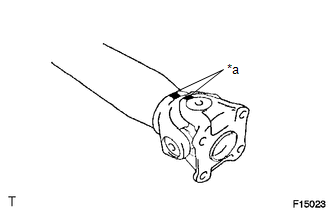
(a) Place matchmarks on the propeller shaft and flange yoke.
Text in Illustration|
*a |
Matchmark |
|
(b) Using a brass bar and a hammer, slightly tap in the spider bearing outer races. |
|
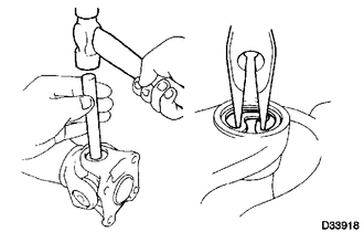
(c) Using needle-nose pliers, remove the 4 snap rings from the grooves.
|
(d) Using SST, push the spider bearing out of the propeller shaft. SST: 09332-25010 HINT: Sufficiently raise the part indicated by (A) so that it does not come into contact with the spider bearing. |
|
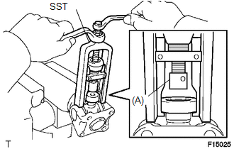
|
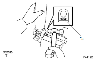
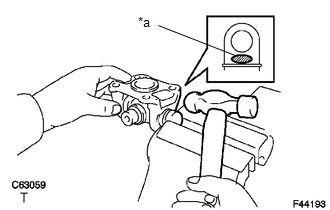
(e) Clamp the spider bearing outer race in a vise and tap off the propeller shaft with a hammer. HINT: Remove the bearing on the opposite side in the same procedure. Text in Illustration
NOTICE: Do not tap the shaft. |
|
|
(f) Install the 2 removed spider bearing outer races onto the spider, and clamp them in a vise. |
|
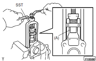
(g) Using SST, push the bearing out of the yoke.
SST: 09332-25010
HINT:
Sufficiently raise the part indicated by (A) so that it does not come into contact with the bearing.
|
(h) Clamp the outer bearing race in a vise and tap off the flange yoke with a hammer. Text in Illustration
|
|
(i) Remove the spider.
 Removal
REMOVAL
PROCEDURE
1. REMOVE FRONT NO. 2 EXHAUST PIPE ASSEMBLY (for 2GR-FKS)
2. REMOVE PROPELLER SHAFT HEAT INSULATOR BRACKET SUB-ASSEMBLY
(a) Remove the 2 bolts and propeller shaft heat insu ...
 Inspection
INSPECTION
PROCEDURE
1. INSPECT FRONT PROPELLER SHAFT ASSEMBLY
(a) Using a dial indicator, check the propeller shaft runout.
Maximum runout:
0.6 mm (0.024 in.)
If the shaft runout is greater ...
Other materials:
System Description
SYSTEM DESCRIPTION
1. POWER WINDOW CONTROL SYSTEM DESCRIPTION
(a) The power window control system controls the power window operation using
the power window regulator motors. The main controls of this system are the power
window regulator master switch assembly (mounted on the driver door), po ...
How To Proceed With Troubleshooting
CAUTION / NOTICE / HINT
HINT:
Use the following procedure to troubleshoot the intuitive parking assist
system.
*: Use the Techstream.
PROCEDURE
1.
VEHICLE BROUGHT TO WORKSHOP
NEXT
...
Parts Location
PARTS LOCATION
ILLUSTRATION
*A
for Vacuum Brake Booster
*B
for Hydraulic Brake Booster
*1
SKID CONTROL ECU (BRAKE ACTUATOR ASSEMBLY)
*2
SKID CONTROL ECU (MASTER CYLINDER SOLENOID)
*3
...
