Toyota Tacoma (2015-2018) Service Manual: Components
COMPONENTS
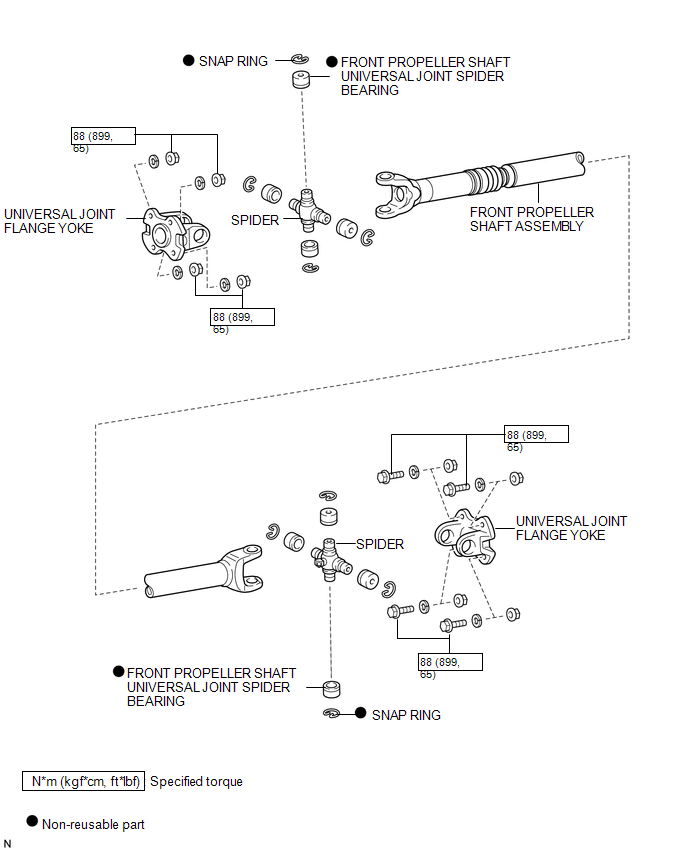
ILLUSTRATION

 Removal
REMOVAL
PROCEDURE
1. REMOVE FRONT NO. 2 EXHAUST PIPE ASSEMBLY (for 2GR-FKS)
2. REMOVE PROPELLER SHAFT HEAT INSULATOR BRACKET SUB-ASSEMBLY
(a) Remove the 2 bolts and propeller shaft heat insu ...
Other materials:
Ptc Heater Relay
Components
COMPONENTS
ILLUSTRATION
Inspection
INSPECTION
PROCEDURE
1. INSPECT PTC HEATER RELAY
(a) Check the resistance.
(1) Measure the resistance according to the value(s) in the table below.
Standard Resistance:
Tester Connection
C ...
Removal
REMOVAL
CAUTION / NOTICE / HINT
HINT:
Use the same procedures for both the LH and RH sides.
The procedure described below is for the LH side.
PROCEDURE
1. REMOVE FRONT DOOR LOWER FRAME BRACKET GARNISH
2. REMOVE FRONT DOOR INSIDE HANDLE BEZEL PLUG
3. REMOVE FRONT ...
Lost Communication with Power Source Control (B278C)
DESCRIPTION
DTC No.
DTC Detection Condition
Trouble Area
B278C
An internal malfunction occurs in the certification ECU (smart key ECU
assembly)
Certification ECU (smart key ECU assembly)
CAUTI ...
