Toyota Tacoma (2015-2018) Service Manual: Removal
REMOVAL
PROCEDURE
1. PRECAUTION
NOTICE:
After turning the ignition switch off, waiting time may be required before disconnecting the cable from the negative (-) battery terminal. Therefore, make sure to read the disconnecting the cable from the negative (-) battery terminal notices before proceeding with work.
Click here .gif)
2. DISCONNECT CABLE FROM NEGATIVE BATTERY TERMINAL
NOTICE:
When disconnecting the cable, some systems need to be initialized after the cable is reconnected.
Click here
3. REMOVE FRONT WHEELS
4. REMOVE NO. 1 ENGINE UNDER COVER SUB-ASSEMBLY
5. REMOVE NO. 2 ENGINE UNDER COVER SUB-ASSEMBLY (w/ Engine Under Cover No, 2)
6. DRAIN DIFFERENTIAL OIL
7. REMOVE FRONT AXLE SHAFT LH NUT
Click here
8. REMOVE FRONT AXLE SHAFT RH NUT
HINT:
Use the same procedure as for the LH side.
9. SEPARATE FRONT STABILIZER LINK ASSEMBLY LH
Click here
10. SEPARATE FRONT STABILIZER LINK ASSEMBLY RH
HINT:
Use the same procedure as for the LH side.
11. SEPARATE FRONT SPEED SENSOR LH
Click here
12. SEPARATE FRONT SPEED SENSOR RH
HINT:
Use the same procedure as for the LH side.
13. SEPARATE TIE ROD END SUB-ASSEMBLY LH
Click here
14. SEPARATE TIE ROD END SUB-ASSEMBLY RH
HINT:
Use the same procedure as for the LH side.
15. SEPARATE FRONT SUSPENSION LOWER ARM LH
Click here
16. SEPARATE FRONT SUSPENSION LOWER ARM RH
HINT:
Use the same procedure as for the LH side.
17. REMOVE FRONT DRIVE SHAFT ASSEMBLY LH
Click here
18. REMOVE FRONT DRIVE SHAFT ASSEMBLY RH
HINT:
Use the same procedure as for the LH side.
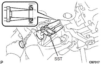
19. REMOVE DIFFERENTIAL SIDE GEAR SHAFT OIL SEAL
|
(a) Using SST, remove the oil seal. SST: 09308-00010 |
|

 Installation
INSTALLATION
PROCEDURE
1. INSTALL DIFFERENTIAL SIDE GEAR SHAFT OIL SEAL
(a) Using SST and a hammer, install a new oil seal.
SST: 09554-30011
(b) Coat the oil seal lip with MP grease.
2. INSTAL ...
Other materials:
System Diagram
SYSTEM DIAGRAM
Transmitting ECU
(Transmitter)
Receiving ECU
Signal
Communication Method
Airbag Sensor Assembly
ECM
Crash detection signal
CAN
Airbag Sensor Assembly
Com ...
Installation
INSTALLATION
PROCEDURE
1. INSTALL FUEL SUCTION TUBE SET GASKET
(a) Ensure gasket groove is clean and free of foreign particles.
(b) Install a new gasket onto the fuel tank.
(c) Make sure that the gasket sits in the groove.
2. INSTALL FUEL SU ...
Removal
REMOVAL
PROCEDURE
1. REMOVE FUEL DELIVERY PIPE ASSEMBLY LH (FUEL PRESSURE SENSOR)
(See page )
NOTICE:
Do not remove the fuel pressure sensor from the fuel delivery pipe sub-assembly
LH.
If a fuel pressure sensor is removed, replace the fuel delivery pipe
sub-assembly LH (fu ...
