Toyota Tacoma (2015-2018) Service Manual: Installation
INSTALLATION
PROCEDURE
1. INSTALL DIFFERENTIAL SIDE GEAR SHAFT OIL SEAL
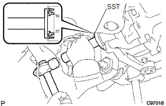
(a) Using SST and a hammer, install a new oil seal.
SST: 09554-30011
(b) Coat the oil seal lip with MP grease.
2. INSTALL FRONT DRIVE SHAFT ASSEMBLY LH
Click here .gif)
3. INSTALL FRONT DRIVE SHAFT ASSEMBLY RH
HINT:
Use the same procedure as for the LH side.
4. INSTALL FRONT SUSPENSION LOWER ARM LH
Click here
5. INSTALL FRONT SUSPENSION LOWER ARM RH
HINT:
Use the same procedure as for the LH side.
6. INSTALL TIE ROD END SUB-ASSEMBLY LH
Click here
7. INSTALL TIE ROD END SUB-ASSEMBLY RH
HINT:
Use the same procedure as for the LH side.
8. INSTALL FRONT SPEED SENSOR LH
Click here
9. INSTALL FRONT SPEED SENSOR RH
HINT:
Use the same procedure as for the LH side.
10. INSTALL FRONT STABILIZER LINK ASSEMBLY LH
Click here
11. INSTALL FRONT STABILIZER LINK ASSEMBLY RH
HINT:
Use the same procedure as for the LH side.
12. INSTALL FRONT AXLE SHAFT LH NUT
Click here
13. INSTALL FRONT AXLE SHAFT RH NUT
HINT:
Use the same procedure as for the LH side.
14. ADD DIFFERENTIAL OIL
Click here
15. INSPECT DIFFERENTIAL OIL
Click here
16. INSTALL NO. 1 ENGINE UNDER COVER SUB-ASSEMBLY
Torque:
30 N·m {306 kgf·cm, 22 ft·lbf}
17. INSTALL NO. 2 ENGINE UNDER COVER SUB-ASSEMBLY (w/ Engine Under Cover No, 2)
Torque:
30 N·m {306 kgf·cm, 22 ft·lbf}
18. INSTALL FRONT WHEELS
Torque:
113 N·m {1152 kgf·cm, 83 ft·lbf}
19. INSPECT AND ADJUST FRONT WHEEL ALIGNMENT
Click here
20. CONNECT CABLE TO NEGATIVE BATTERY TERMINAL
Torque:
5.4 N·m {55 kgf·cm, 48 in·lbf}
NOTICE:
When disconnecting the cable, some systems need to be initialized after the cable is reconnected.
Click here
21. CHECK VSC SENSOR SIGNAL (for Hydraulic Brake Booster)
Click here
22. CHECK VSC SENSOR SIGNAL (for Vacuum Brake Booster)
Click here
 Removal
REMOVAL
PROCEDURE
1. PRECAUTION
NOTICE:
After turning the ignition switch off, waiting time may be required before disconnecting
the cable from the negative (-) battery terminal. Therefore, make ...

Other materials:
Windshield wipers and washer
■ Without intermittent type
Type A
Low speed windshield wiper
operation
High speed windshield wiper operation
Temporary operation
Washer operation
Type B
Low speed windshield wiper operation
High speed windshield wiper operation
Temporary operation
Washer op ...
Tire Pressure Monitor Receiver Communication Stop (B1247)
DESCRIPTION
The main body ECU (multiplex network body ECU) and tire pressure warning ECU
and receiver are connected using 2 direct lines that they use to communicate with
each other.
DTC No.
Detection Item
DTC Detection Condition
Trouble Area
...
Vehicle Information Not Obtained (C1A02)
DESCRIPTION
When a new millimeter wave radar sensor assembly is installed, it receives vehicle
specification information (destination, steering wheel position, 2WD or 4WD, etc.)
from the main body ECU (multiplex network body ECU) and stores the information.
DTC C1A02 is stored when the millime ...
