Toyota Tacoma (2015-2018) Service Manual: Rear Speed Sensor
Removal
REMOVAL
PROCEDURE
1. PRECAUTION
NOTICE:
After turning the ignition switch off, waiting time may be required before disconnecting the cable from the negative (-) battery terminal.
Therefore, make sure to read the disconnecting the cable from the negative (-) battery terminal notices before proceeding with work.
Click here .gif)
2. DISCONNECT CABLE FROM NEGATIVE BATTERY TERMINAL
NOTICE:
When disconnecting the cable, some systems need to be initialized after the cable is reconnected.
Click here
3. REMOVE REAR SPEED SENSOR
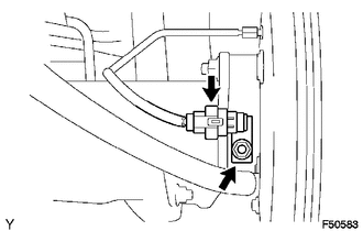
(a) Disconnect the speed sensor connector.
(b) Remove the nut and speed sensor rear.
NOTICE:
- Do not attach any foreign matter to the sensor tip.
- Ensure that no foreign matter enters the sensor installation hole.
Installation
INSTALLATION
PROCEDURE
1. INSTALL REAR SPEED SENSOR
.png)
(a) Install the rear speed sensor with the nut.
Torque:
8.0 N·m {82 kgf·cm, 71 in·lbf}
NOTICE:
Make sure that the sensor tip is clean.
(b) Connect the speed sensor connector.
2. CONNECT CABLE TO NEGATIVE BATTERY TERMINAL
Torque:
5.4 N·m {55 kgf·cm, 48 in·lbf}
NOTICE:
When disconnecting the cable, some systems need to be initialized after the cable is reconnected.
Click here .gif)
3. CHECK VSC SENSOR SIGNAL (for Hydraulic Brake Booster)
Click here
4. CHECK VSC SENSOR SIGNAL (for Vacuum Brake Booster)
Click here
 Multi-terrain Select Switch
Components
COMPONENTS
ILLUSTRATION
Removal
REMOVAL
PROCEDURE
1. REMOVE MULTI-TERRAIN SELECT SWITCH (DRIVE MONITOR SWITCH)
(a) Disengage the 2 claws to remove the multi-terrain ...

Other materials:
Installation
INSTALLATION
PROCEDURE
1. INSPECT AND ADJUST BRAKE BOOSTER PUSH ROD
NOTICE:
The brake booster interior must not be a vacuum when adjusting the booster. Stop
the engine and depress the brake pedal several times until there is no vacuum in
the booster.
HINT:
Adjust the booster push rod when ...
ABS Warning Light does not Come ON
DESCRIPTION
Refer to ABS Warning Light Remains ON (See page
).
WIRING DIAGRAM
Refer to ABS Warning Light Remains ON (See page
).
CAUTION / NOTICE / HINT
NOTICE:
When replacing the skid control ECU (master cylinder solenoid), perform
calibration (See page
).
Inspect the ...
Lost Communication with ECM (C1437)
DESCRIPTION
The skid control ECU (master cylinder solenoid) receives signals from the ECM
via the CAN communication system.
DTC Code
DTC Detection Condition
Trouble Area
C1437
When the IG1 terminal voltage is 10 V or higher and the veh ...
