Toyota Tacoma (2015-2018) Service Manual: Installation
INSTALLATION
CAUTION / NOTICE / HINT
HINT:
- Use the same procedure for both the RH and LH sides.
- The procedure described below is for the LH side.
PROCEDURE
1. INSTALL FRONT SHOULDER BELT ANCHOR ADJUSTER ASSEMBLY
|
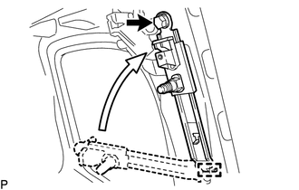
(a) As shown in the illustration, engage the 2 guides to install the front shoulder belt anchor adjuster assembly with the bolt. Torque: 42 N·m {428 kgf·cm, 31 ft·lbf} |
|
2. INSTALL FRONT SEAT OUTER BELT ASSEMBLY
|
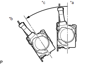
(a) Check the angle of inclination required to lock the retractor. Text in Illustration
(1) When the inclination of the retractor is 15° or less, check that the belt can be pulled from the retractor. When the inclination of the retractor is over 45°, check that the belt locks. NOTICE: Do not disassemble the retractor. If operation is not as specified, replace the front seat outer belt assembly. |
|
|
(b) Engage the 2 guides to temporarily install the front seat outer belt assembly with the 2 bolts. |
|
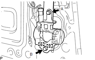
(c) Tighten bolt A, and then tighten bolt B.
Torque:
12.5 N·m {127 kgf·cm, 9 ft·lbf}
(for bolt A)
42 N·m {428 kgf·cm, 31 ft·lbf}
(for bolt B)
|
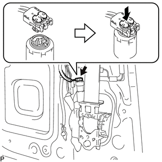
(d) Connect the pretensioner connector and lock the locking button as shown in the illustration. |
|
(e) Connect the shoulder anchor with the nut.
Torque:
42 N·m {428 kgf·cm, 31 ft·lbf}
(f) Check that the shoulder anchor rotates smoothly.
(g) Connect the floor anchor of the front seat outer belt assembly with the bolt.
(h) Check the ELR lock.
NOTICE:
The check should be performed with the front seat outer belt assembly installed.
(1) With the belt installed, check that the belt locks when it is pulled out quickly.
If the operation is not as specified, replace the front seat outer belt assembly.
(i) Remove the bolt to disconnect the floor anchor.
3. INSTALL ACCESS PANEL INSIDE HANDLE SUB-ASSEMBLY
Click here .gif)
4. INSTALL REAR DOOR TRIM BOARD SUB-ASSEMBLY
Click here
5. INSTALL DOOR PULL HANDLE
Click here
6. INSTALL ACCESS PANEL INSIDE HANDLE BEZEL
Click here
7. INSTALL LAP BELT OUTER ANCHOR COVER
Click here
8. INSTALL ACCESS PANEL REAR WEATHERSTRIP
Click here
9. CONNECT CABLE TO NEGATIVE BATTERY TERMINAL
Torque:
5.4 N·m {55 kgf·cm, 48 in·lbf}
NOTICE:
When disconnecting the cable, some systems need to be initialized after the cable is reconnected.
Click here
10. INSPECT SRS WARNING LIGHT
Click here
 Components
COMPONENTS
ILLUSTRATION
ILLUSTRATION
...
 Removal
REMOVAL
CAUTION / NOTICE / HINT
HINT:
Use the same procedure for both the RH and LH sides.
The procedure described below is for the LH side.
PROCEDURE
1. PRECAUTION
NOTICE:
Af ...
Other materials:
Removal
REMOVAL
PROCEDURE
1. REMOVE MILLIMETER WAVE RADAR WIRE
(a) for Type A:
(1) Disconnect the 2 connectors.
(2) Using a clip remover, disengage the 4 clamps to remove the millimeter
wave radar wire.
(b) for Type B:
(1) Disc ...
Diagnostic Trouble Code Chart
DIAGNOSTIC TROUBLE CODE CHART
Forward Recognition Camera System
DTC No.
Detection Item
Link
C1A0A
Front Radar Sensor Region Code Mismatch
C1A47
Steering Angle Sensor
...
Engine Coolant Temperature Receiver Gauge Malfunction
DESCRIPTION
In this circuit, the meter CPU receives engine coolant temperature signals from
the ECM using the CAN communication system (CAN V1 Bus). The meter CPU displays
engine coolant temperature that is calculated based on the data received from the
ECM.
WIRING DIAGRAM
CAUTION / NOTIC ...
