Toyota Tacoma (2015-2018) Service Manual: Removal
REMOVAL
PROCEDURE
1. PRECAUTION
NOTICE:
After turning the ignition switch off, waiting time may be required before disconnecting the cable from the negative (-) battery terminal.
Therefore, make sure to read the disconnecting the cable from the negative (-) battery terminal notices before proceeding with work.
Click here .gif)
2. DISCONNECT CABLE FROM NEGATIVE BATTERY TERMINAL
NOTICE:
When disconnecting the cable, some systems need to be initialized after the cable is reconnected.
Click here
3. REMOVE REAR WHEEL
4. DRAIN BRAKE FLUID
5. REMOVE REAR BRAKE DRUM SUB-ASSEMBLY
Click here
6. REMOVE FRONT BRAKE SHOE
Click here
7. REMOVE REAR BRAKE SHOE
Click here
8. REMOVE REAR SPEED SENSOR
Click here
9. SEPARATE PARKING BRAKE CABLE ASSEMBLY NO. 3
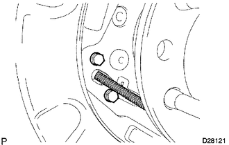
(a) Remove the 2 bolts and disconnect the parking brake cable from the backing plate.
10. SEPARATE REAR BRAKE TUBE NO. 8
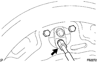
(a) Using a union nut wrench, separate the brake tube, and use a container to catch the brake fluid as it flows out.
11. REMOVE REAR AXLE SHAFT WITH BACKING PLATE
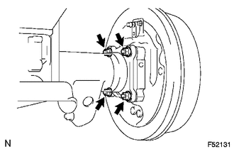
(a) Remove the 4 nuts and rear axle shaft with backing plate.
(b) Remove the O-ring.
12. REMOVE REAR AXLE SHAFT OIL SEAL
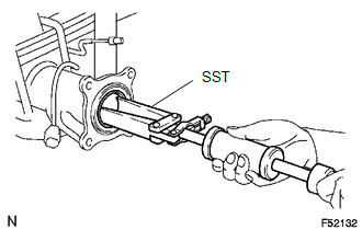
(a) Using SST, remove the oil seal.
SST: 09308-00010
 Inspection
INSPECTION
PROCEDURE
1. INSPECT REAR AXLE SHAFT
(a) Using a dial indicator, measure the runout of the shaft and flange.
Maximum runout:
Shaft runout: 1.5 mm (0.0591 in.)
Flange runout: 0.05 m ...
 Installation
INSTALLATION
PROCEDURE
1. INSTALL REAR AXLE SHAFT OIL SEAL
(a) Using SST and a hammer, install a new oil seal.
SST: 09950-60020
09951-00770
SST: 09950-70010
09951-07150
2. INSTALL REAR AXLE ...
Other materials:
Problem Symptoms Table
PROBLEM SYMPTOMS TABLE
NOTICE:
When replacing the skid control ECU (brake actuator assembly), sensor, etc.,
turn the ignition switch off.
HINT:
Use the table below to help determine the cause of problem symptoms.
If multiple suspected areas are listed, the potential causes of the s ...
Front Occupant Classification Sensor LH Collision Detection (B1785)
DESCRIPTION
DTC B1785 is set when the occupant detection ECU receives a collision detection
signal, which is sent by the occupant classification sensor front LH when an accident
occurs.
DTC B1785 is also set when the front seat with adjuster frame assembly RH is
subjected to a strong impact, ...
Terminals Of Ecu
TERMINALS OF ECU
1. REAR TELEVISION CAMERA ASSEMBLY
(a) Disconnect the T22 television camera assembly connector.
(b) Measure the voltage and resistance according to the value(s) in the table
below.
Terminal No. (Symbol)
Wiring Color
Terminal Description
...
