Toyota Tacoma (2015-2018) Service Manual: Parts Location
PARTS LOCATION
ILLUSTRATION
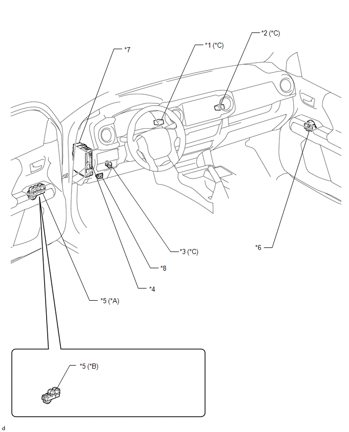
|
*A |
for Double Cab |
*B |
for Access Cab |
|
*C |
w/ Back Door Power Window |
- |
- |
|
*1 |
NO. 1 BACK PANEL PELAY |
*2 |
NO. 2 BACK PANEL RELAY |
|
*3 |
REAR NO. 2 POWER WINDOW REGULATOR SWITCH ASSEMBLY |
*4 |
MAIN BODY ECU(MULTIPLEX NETWORK BODY ECU) |
|
*5 |
POWER WINDOW REGULATOR MASTER SWITCH ASSEMBLY |
*6 |
FRONT POWER WINDOW REGULATOR SWTCH ASSEMBLY RH |
|
*7 |
DRIVER SIDE JUNCTION BLOCK - PWR RELAY - POWER NO. 2 FUSE - DOOR F/R FUSE - DOOR F/L FUSE - POWER NO. 1 FUSE - DOOR R/L FUSE - MPX-B FUSE |
*8 |
DLC3 |
ILLUSTRATION
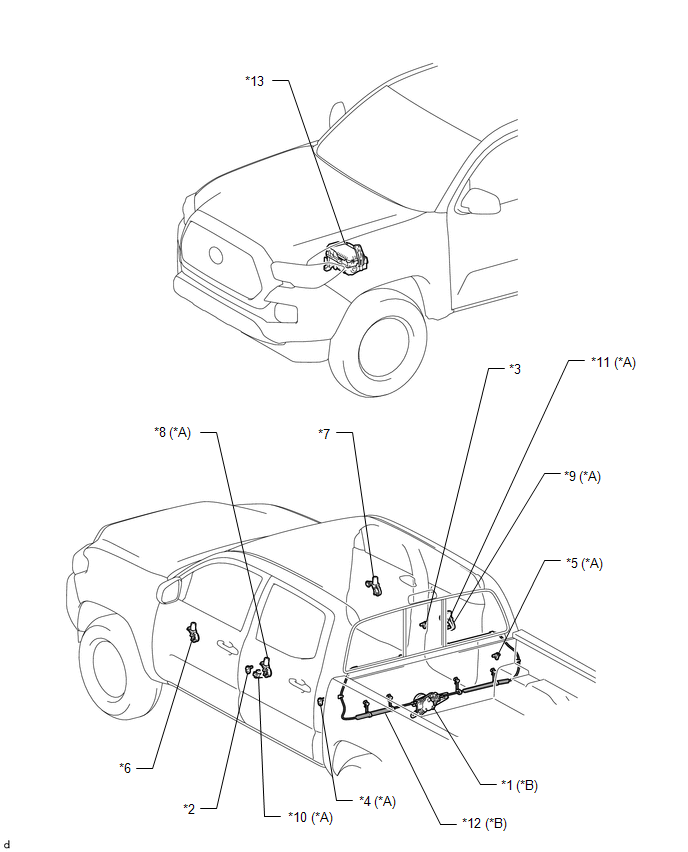
|
*A |
for Double Cab |
*B |
w/ Back Door Power Window |
|
*1 |
POWER WINDOW REGULATOR MOTOR ASSEMBLY |
*2 |
FRONT DOOR COURTESY LIGHT SWITCH ASSEMBLY LH |
|
*3 |
FRONT DOOR COURTESY LIGHT SWITCH ASSEMBLY RH |
*4 |
REAR DOOR COURTESY LIGHT SWITCH ASSEMBLY LH |
|
*5 |
REAR DOOR COURTESY LIGHT SWITCH ASSEMBLY RH |
*6 |
FRONT POWER WINDOW REGULATOR MOTOR ASSEMBLY LH |
|
*7 |
FRONT POWER WINDOW REGULATOR MOTOR ASSEMBLY RH |
*8 |
REAR POWER WINDOW REGULATOR MOTOR ASSEMBLY LH |
|
*9 |
REAR POWER WINDOW REGULATOR MOTOR ASSEMBLY RH |
*10 |
REAR POWER WINDOW REGULATOR SWITCH ASSEMBLY LH |
|
*11 |
REAR POWER WINDOW REGULATOR SWITCH ASSEMBLY RH |
*12 |
DOOR WINDOW REGULATOR CABLE SUB-ASSEMBLY |
|
*13 |
ENGINE ROOM RELAY BLOCK - J/B-B FUSE |
- |
- |

 Precaution
PRECAUTION
1. EXPRESSIONS OF IGNITION SWITCH
(a) The type of ignition switch used on this model differs according to the specifications
of the vehicle. The expressions listed in the table below ar ...
Other materials:
Pressure Control Solenoid "C" Performance (Shift Solenoid Valve SL3) (P0796)
SYSTEM DESCRIPTION
The ECM uses the vehicle speed signal and signals from the transmission revolution
sensors (NT, SP2) to detect the actual gear (1st, 2nd, 3rd, 4th, 5th or 6th gear).
The ECM compares the actual gear with the shift schedule in the ECM memory to
detect mechanical problems of t ...
On-vehicle Inspection
ON-VEHICLE INSPECTION
PROCEDURE
1. CHECK FUEL PUMP OPERATION AND INSPECT FOR FUEL LEAK
(a) Connect the Techstream to the DLC3.
(1) Turn the ignition switch to ON.
NOTICE:
Do not start the engine.
(2) Turn the Techstream on.
(3) Enter the following menus: Powertrain / Engine / Active Test / C ...
Connecting BluetoothÂź
The following can be performed using BluetoothÂź wireless communication: ■
A portable audio player can be operated and listened to via multimedia system
■ Hands-free phone calls can be made via a cellular phone
In order to use wireless communication, register and connect a Bluetooth ...
