Toyota Tacoma (2015-2018) Service Manual: Fog Light Relay
Inspection
INSPECTION
PROCEDURE
1. INSPECT FOG LIGHT RELAY
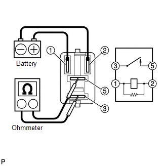
(a) Check the resistance.
(1) Using an ohmmeter, measure the resistance between the terminals.
Standard:
|
Tester Connection |
Specified Condition |
|---|---|
|
3-5 |
10 kΩ or higher |
|
3-5 |
Below 1 Ω (When battery voltage applied to terminals 1 and 2) |
If the result is not as specified, replace the fog light relay.
 Installation
INSTALLATION
CAUTION / NOTICE / HINT
HINT:
Use the same procedure for both the LH and RH sides.
The procedure described below is for the LH side.
PROCEDURE
1. INSTALL FOG LAMP A ...
 Front Door Courtesy Switch
Inspection
INSPECTION
PROCEDURE
1. INSPECT FRONT DOOR COURTESY SWITCH
(a) Check the resistance.
(1) Measure the resistance using an ohmmeter, and check the results in accordance
with the valu ...
Other materials:
Installation
INSTALLATION
PROCEDURE
1. INSTALL FRONT DIFFERENTIAL CARRIER ASSEMBLY
(a) Connect the actuator hose and connector.
(b) Install the No. 1 mounting support with the 3 bolts.
Torque:
186 N·m {1899 kgf·cm, 138 ft·lbf}
(c) Install the No. 2 mounting support with the 2 bolts.
Torque:
160 N ...
Removal
REMOVAL
PROCEDURE
1. PRECAUTION
NOTICE:
After turning the ignition switch off, waiting time may be required before disconnecting
the cable from the negative (-) battery terminal. Therefore, make sure to read the
disconnecting the cable from the negative (-) battery terminal notices before pr ...
How To Proceed With Troubleshooting
CAUTION / NOTICE / HINT
HINT:
Use these procedures to troubleshoot the power window control system.
PROCEDURE
1.
VEHICLE BROUGHT TO WORK SHOP
NEXT
2.
CUSTOMER ...
