Toyota Tacoma (2015-2018) Service Manual: Ignition Hold Monitor Malfunction (B2271)
DESCRIPTION
This DTC is stored when a malfunction in the IG circuit or IG hold circuit in the certification ECU (smart key ECU assembly) is detected.
HINT:
When the cable is disconnected and reconnected to the negative (-) battery terminal, the power source mode returns to the state it was in before the cable was disconnected.
|
DTC Code |
DTC Detection Condition |
Trouble Area |
DTC Output Confirmation Operation |
|---|---|---|---|
|
B2271 |
When either of the following conditions is met (1-trip detection logic*):
|
|
IG ON |
- *: Only detected while a malfunction is present and the engine switch is on (IG)
HINT:
- The IG circuits activate the IG relays.
- After the IG circuits turn on, even if the CPU operates incorrectly, the IG hold circuit maintains the power source mode in on (IG).
|
Vehicle Condition when Malfunction Detected |
Fail-safe Function when Malfunction Detected |
|---|---|
|
The engine switch cannot be turned on (IG) (the engine cannot be started). |
The power source mode cannot be changed to on (IG). |
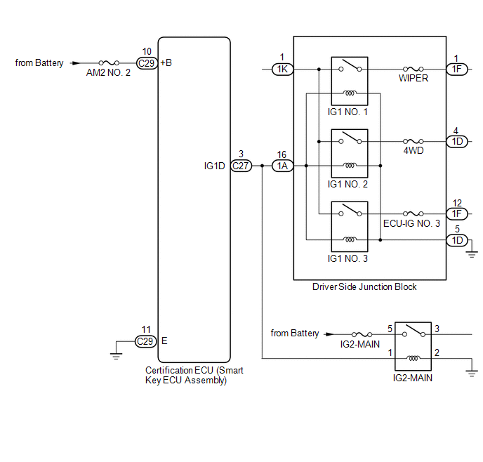
WIRING DIAGRAM
CAUTION / NOTICE / HINT
NOTICE:
- When using the Techstream with the engine switch off, connect the Techstream to the DLC3 and turn a courtesy light switch on and off at intervals of 1.5 seconds or less until communication between the Techstream and the vehicle begins. Then select the vehicle type under manual mode and enter the following menus: Body Electrical / Smart Key. While using the Techstream, periodically turn a courtesy light switch on and off at intervals of 1.5 seconds or less to maintain communication between the Techstream and the vehicle.
- The smart key system (for Start Function) uses a multiplex communication
system (LIN communication system) and the CAN communication system. Inspect
the communication function by following How to Proceed with Troubleshooting.
Click here
.gif)
Troubleshoot the smart key system (for Start Function) after confirming that the communication systems are functioning properly.
- Before replacing the certification ECU (smart key ECU assembly), refer
to the smart key system (for Start Function) precaution (See page
).
- Inspect the fuses of circuits related to this system before performing the following inspection procedure.
- After performing repairs, perform the operation that fulfills the DTC output confirmation operation, and then confirm that no DTCs are output again.
|
DTC |
Data List Item |
Active Test Item |
|---|---|---|
|
B2271 |
Power Source Control
Starting Control
|
- |
PROCEDURE
|
1. |
CHECK HARNESS AND CONNECTOR (POWER SOURCE) |
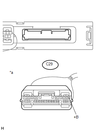
(a) Disconnect the certification ECU (smart key ECU assembly) connector.
|
(b) Measure the voltage according to the value(s) in the table below. Standard Voltage:
|
|
| NG | .gif) |
REPAIR OR REPLACE HARNESS OR CONNECTOR IN CIRCUIT CONNECTED TO POWER SOURCE |
|
.gif)
|
2. |
CHECK HARNESS AND CONNECTOR (GROUND) |
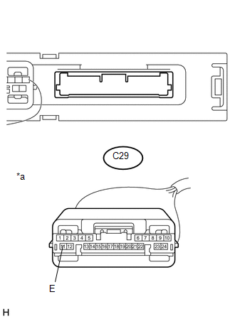
(a) Disconnect the certification ECU (smart key ECU assembly) connector.
|
(b) Measure the resistance according to the value(s) in the table below. Standard Resistance:
|
|
| NG | |
REPAIR OR REPLACE HARNESS OR CONNECTOR |
|
|
3. |
CHECK CERTIFICATION ECU (SMART KEY ECU ASSEMBLY) |
|
(a) Reconnect the certification ECU (smart key ECU assembly) connector. |
|
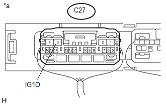
(b) Measure the voltage according to the value(s) in the table below.
Standard Voltage:
|
Tester Connection |
Condition |
Specified Condition |
|---|---|---|
|
C27-3 (IG1D) - Body ground |
Engine switch on (ACC) → Engine switch on (IG) |
1 V or less → 9 V or higher |
|
*a |
Component with harness connected (Certification ECU (Smart Key ECU Assembly)) |
| OK | |
USE SIMULATION METHOD TO CHECK |
| NG | |
REPLACE CERTIFICATION ECU (SMART KEY ECU ASSEMBLY) |
 Vehicle Speed Signal Malfunction (B2282,B2283)
DESCRIPTION
DTC B2282 is stored when the vehicle speed signal sent by the combination meter
assembly via direct line and the vehicle speed signal sent via CAN communication
do not match.
DTC B22 ...
 ACC Monitor Malfunction (B2274)
DESCRIPTION
This DTC is stored when a malfunction in the ACC output circuit is detected.
The ACC output circuit is the circuit that goes from the ACC output terminal of
the certification ECU (sma ...
Other materials:
Components
COMPONENTS
ILLUSTRATION
*1
FORWARD RECOGNITION CAMERA
*2
FORWARD RECOGNITION LATCH
*3
NO. 1 FORWARD RECOGNITION COVER
-
-
...
Installation
INSTALLATION
PROCEDURE
1. INSTALL INSTRUMENT PANEL SUB-ASSEMBLY
(a) Engage the 5 guides to install the instrument panel sub-assembly.
(b) Engage the clamps and connect the connectors.
(c) Install the nut <G>.
(d) Install the 8 bolts <A>.
(e) Install the 2 bolts <B> or 2 bo ...
Precaution
PRECAUTION
1. IGNITION SWITCH EXPRESSIONS
(a) The type of ignition switch used on this model differs according to the specifications
of the vehicle. The expressions listed in the table below are used in this section.
Expression
Ignition Switch (Position)
Engine ...
