Toyota Tacoma manuals

Toyota Tacoma (2015-2018) Service Manual: Reassembly

REASSEMBLY

PROCEDURE

1. INSTALL CONSOLE COMPARTMENT DOOR HINGE SUB-ASSEMBLY

(a) Engage the 2 guides to install the console compartment door hinge sub-assembly.

(b) Install the 4 screws.

(c) Engage the 2 guides and 4 claws to install the console compartment door moulding cover.

2. INSTALL CONSOLE COMPARTMENT OUTER DOOR

(a) Engage the 2 guides and 2 claws to install the console compartment outer door.

(b) Install the 4 screws.

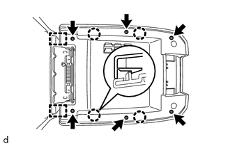
3. INSTALL CONSOLE COMPARTMENT DOOR SUB-ASSEMBLY

(a) Engage the 2 guides and 4 claws to install the console compartment door sub-assembly.

(b) Install the 6 screws.

(c) Engage the 2 guides to install the console compartment door lock lever.

(d) Install the 2 screws.

4. INSTALL CONSOLE COMPARTMENT DOOR CUSHION

HINT:

Use the same procedure as for the opposite side.

(a) Engage the claw to install the console compartment door cushion.

Installation
INSTALLATION PROCEDURE 1. INSTALL FRONT CONSOLE BOX (for Automatic Transmission) (a) When installing a new front console box: Text in Illustration *a ...

Front Floor Footrest
Components COMPONENTS ILLUSTRATION Installation INSTALLATION PROCEDURE 1. INSTALL FRONT FLOOR FOOTREST (a) Engage the 2 clips to install the front floor footrest. ...

Other materials:

Inspection
INSPECTION PROCEDURE 1. INSPECT FRONT SUSPENSION LOWER ARM (a) Flip the ball joint stud back and forth 5 times, as shown in the illustration, before installing the nut. (b) Using a torque wrench, turn the nut continuously at a rate of 2 to 4 seconds per turn and take the torque reading on ...

Microphone Circuit between Microphone and Radio Receiver
DESCRIPTION The navigation receiver assembly and telephone microphone assembly are connected to each other using the microphone connection detection signal lines. Using this circuit, the navigation receiver assembly sends power to the telephone microphone assembly and the telephone microphone ...

VSC Buzzer Circuit
DESCRIPTION The skid control ECU (master cylinder solenoid) is connected to the combination meter via CAN communication. The combination meter has a built-in VSC warning buzzer: Sounds intermittently to inform the driver if the temperature of hydraulic brake booster has increased exc ...

В© 2011-2026 Copyright www.ttguide.net