Toyota Tacoma (2015-2018) Service Manual: Front Floor Footrest
Components
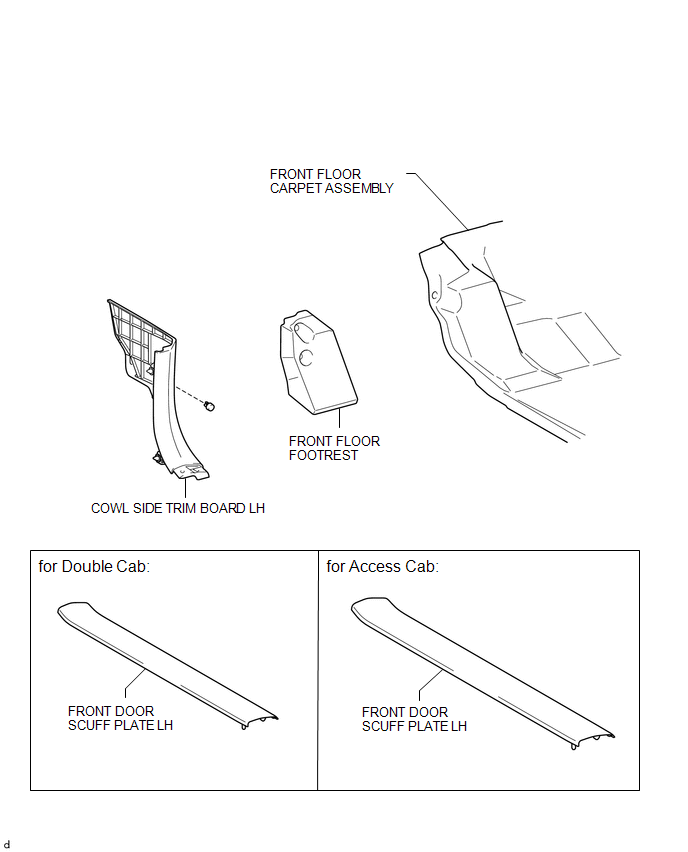
COMPONENTS
ILLUSTRATION
Installation
INSTALLATION
PROCEDURE
1. INSTALL FRONT FLOOR FOOTREST
|
(a) Engage the 2 clips to install the front floor footrest. |
|
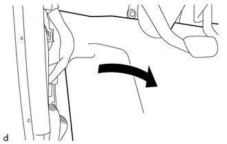
2. INSTALL FRONT FLOOR CARPET ASSEMBLY
|
(a) Return the front floor carpet assembly as shown in the illustration. |
|
3. INSTALL COWL SIDE TRIM BOARD LH
.gif)
4. INSTALL FRONT DOOR SCUFF PLATE LH (for Double Cab)
5. INSTALL FRONT DOOR SCUFF PLATE LH (for Access Cab)
Removal
REMOVAL
PROCEDURE
1. REMOVE FRONT DOOR SCUFF PLATE LH (for Double Cab)
.gif)
2. REMOVE FRONT DOOR SCUFF PLATE LH (for Access Cab)
3. REMOVE COWL SIDE TRIM BOARD LH
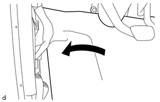
4. SEPARATE FRONT FLOOR CARPET ASSEMBLY
|
(a) Peel back the front floor carpet assembly as shown in the illustration. |
|
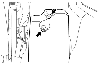
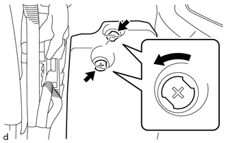
5. REMOVE FRONT FLOOR FOOTREST
|
(a) Rotate the 2 clips counterclockwise to remove the front floor footrest as shown in the illustration. |
|
 Reassembly
REASSEMBLY
PROCEDURE
1. INSTALL CONSOLE COMPARTMENT DOOR HINGE SUB-ASSEMBLY
(a) Engage the 2 guides to install the console compartment door hinge
sub-assembly.
...
 Rear Console Box
Components
COMPONENTS
ILLUSTRATION
ILLUSTRATION
Installation
INSTALLATION
PROCEDURE
1. INSTALL BOX BOTTOM MAT
(a) Engage the 10 guides and install the 2 box bottom mats.
2. INSTALL CO ...
Other materials:
Installation
INSTALLATION
PROCEDURE
1. INSTALL ROOF HEADLINING ASSEMBLY
(a) Insert the roof headlining assembly into the vehicle from the door.
NOTICE:
Check that the corners of the roof headlining assembly are not
folded, twisted or otherwise deformed and that none of the ...
On-vehicle Inspection
ON-VEHICLE INSPECTION
PROCEDURE
1. INSPECT DRIVE BELT
(a) Visually check the belt for defects, such as excessive wear and frayed cords.
If any defects are found, replace the drive belt.
HINT:
Replace the belt if there are any missing ribs.
2. BLEED POWER STEERING SYSTEM
(a) Check the fluid ...
Tire Pressure Monitor ECU Communication Stop Mode
DESCRIPTION
Detection Item
Symptom
Trouble Area
Tire Pressure Monitor ECU Communication Stop Mode
Either condition is met:
Communication stop for "Tire Pressure2" is indicated on the
"Communication Bus C ...
