Toyota Tacoma (2015-2018) Service Manual: Reassembly
REASSEMBLY
PROCEDURE
1. INSTALL NO. 3 REAR BODY NAME PLATE (for 2GR-FKS)
.gif)
2. INSTALL NO. 2 REAR BODY NAME PLATE (for 4WD)
3. INSTALL SIDE GATE SUPPORT FEMALE HINGE RH
|
(a) Engage the claw to install the side gate support female hinge RH. |
|
.png)
4. INSTALL TAIL GATE HINGE ASSEMBLY RH
|
(a) Using a T40 "TORX" socket wrench, install the tail gate hinge assembly RH with the bolt and 2 screws. Torque: Bolt : 27 N·m {275 kgf·cm, 20 ft·lbf} Screw : 27 N·m {275 kgf·cm, 20 ft·lbf} |
|
.png)
5. INSTALL TAIL GATE HINGE ASSEMBLY LH
|
(a) Using a T40 "TORX" socket wrench, install the tail gate hinge assembly LH with the bolt and 2 screws. Torque: Bolt : 27 N·m {275 kgf·cm, 20 ft·lbf} Screw : 27 N·m {275 kgf·cm, 20 ft·lbf} |
|
.png)
6. INSTALL TAIL GATE STAY ASSEMBLY
|
(a) Using a T40 "TORX" socket wrench, install the tail gate stay assembly with the tail gate stay shaft and washer. Torque: 26 N·m {260 kgf·cm, 19 ft·lbf} HINT: Use the same procedure for the LH side and RH side. |
|
.png)
7. INSTALL TAIL GATE STAY STOPPER
|
(a) Using a T40 "TORX" socket wrench, install the tail gate stopper with the tail gate stay shaft. Torque: 26 N·m {260 kgf·cm, 19 ft·lbf} HINT: Use the same procedure for the LH side and RH side. |
|
.png)
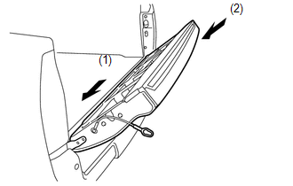
8. INSTALL TAIL GATE
|
(a) Install the tail gate onto the vehicle by engaging the hinge on the left side first and then the hinge on the right side. NOTICE: Be careful not to drop the tail gate. |
|
|
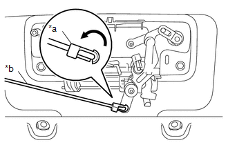
(b) Engage the tail gate stay to the tail gate stay stopper as shown in the illustration. HINT: Use the same procedure for the LH side and RH side. |
|
|
(c) Engage the 2 guides and 2 claws to connect the wire harness from the tail gate. |
|
.png)
(d) Engage the clamp.
Text in Illustration|
*a |
Guide |
|
*b |
Clamp |
|
(e) Engage the clamp. |
|
.png)
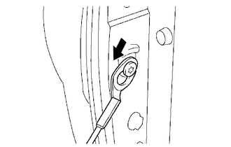
9. INSTALL TAIL GATE LOCK STRIKER
|
(a) Using a T40 "TORX" socket wrench, install the tail gate lock striker with the 2 bolts. Torque: 29 N·m {296 kgf·cm, 21 ft·lbf} HINT: Use the same procedure for the LH side and RH side. |
|
.png)
10. INSTALL TAIL GATE HANDLE ASSEMBLY
|
(a) Engage the guide to install the tail gate handle assembly. |
|
.png)
(b) Install the 2 bolts.
Torque:
5.5 N·m {56 kgf·cm, 49 in·lbf}
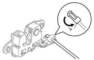
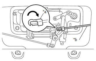
11. INSTALL TAIL GATE LOCK CONTROL LINK
|
(a) Rotate the snap as shown in the illustration to engage the snap to install the tail gate lock control link to tail gate lock assembly LH. Text in Illustration
HINT: Use the same procedure for the LH side and RH side. |
|
12. INSTALL TAIL GATE LOCK ASSEMBLY LH
|
(a) Using a T40 "TORX" socket wrench, install the tail gate lock assembly LH with the 2 bolts. Torque: 29 N·m {296 kgf·cm, 21 ft·lbf} |
|
.png)
(b) Engage the clamp.
|
(c) Rotate the snap as shown in the illustration to engage the snap to install the tail gate lock control link to tail gate handle assembly. Text in Illustration
|
|
13. INSTALL TAIL GATE LOCK ASSEMBLY RH
|
(a) Using a T40 "TORX" socket wrench, install the tail gate lock assembly RH with the 2 bolts. Torque: 29 N·m {296 kgf·cm, 21 ft·lbf} |
|
.png)
(b) Engage the clamp.
|
(c) Rotate the snap as shown in the illustration to engage the snap to install the tail gate lock control link to tail gate handle assembly. Text in Illustration
|
|
14. INSTALL REAR TELEVISION CAMERA ASSEMBLY
15. INSTALL TAIL GATE SERVICE HOLE COVER
|
(a) Using a T30 "TORX" socket wrench, install the tail gate service hole cover with the 8 screws. |
|
.png)
16. INSTALL TAIL GATE PROTECTOR
(See page )
 Disassembly
DISASSEMBLY
PROCEDURE
1. REMOVE TAIL GATE PROTECTOR
(See page )
2. REMOVE TAIL GATE SERVICE HOLE COVER
(a) Using a T30 "TORX" socket wrench, remove the 8 screws and tail gat ...
 Tonneau Cover Assembly
Removal
REMOVAL
PROCEDURE
1. REMOVE TOP COVER SUB-ASSEMBLY
(a) Open the cover.
(b) Remove the bolt and top cover sub-assembly.
2. REMOVE RE ...
Other materials:
Disassembly
DISASSEMBLY
PROCEDURE
1. REMOVE FRONT LICENSE PLATE BRACKET
(a) Remove the 2 screws and front license plate bracket.
2. REMOVE NO. 4 ENGINE ROOM WIRE (w/ Fog Light)
(a) Disconnect the 2 connectors.
...
Precaution
PRECAUTION
1. IGNITION SWITCH EXPRESSION
(a) The type of ignition switch used on this model differs depending on the specifications
of the vehicle.
The expressions listed in the table below are used in this section.
Expression
Ignition Switch (Position)
Engine ...
Portable Player cannot be Registered
CAUTION / NOTICE / HINT
HINT:
Some versions of "Bluetooth" compatible audio players may not function, or the
function may be limited using the radio and display receiver assembly, even if the
portable audio player itself can play files (See page
).
PROCEDURE
1.
...
