Toyota Tacoma (2015-2018) Service Manual: Tonneau Cover Assembly
Removal
REMOVAL
PROCEDURE
1. REMOVE TOP COVER SUB-ASSEMBLY
|
(a) Open the cover. |
|
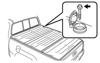
(b) Remove the bolt and top cover sub-assembly.
2. REMOVE REAR BODY SIDE PANEL PROTECTOR
Click here .gif)
Installation
INSTALLATION
PROCEDURE
1. INSTALL REAR BODY SIDE PANEL PROTECTOR
Click here .gif)
2. INSTALL TOP COVER SUB-ASSEMBLY
(a) Install the top cover sub-assembly with the bolt.
Torque:
27.3 N┬Ęm {278 kgf┬Ęcm, 20 ft┬Ęlbf}
(b) Close the cover.
 Reassembly
REASSEMBLY
PROCEDURE
1. INSTALL NO. 3 REAR BODY NAME PLATE (for 2GR-FKS)
2. INSTALL NO. 2 REAR BODY NAME PLATE (for 4WD)
3. INSTALL SIDE GATE SUPPORT FEMALE HINGE RH
(a) Engage ...

Other materials:
Panel Switches do not Function
PROCEDURE
1.
CHECK PANEL SWITCH
(a) Check for foreign matter around the switches that might prevent operation.
OK:
No foreign matter is found.
NG
REMOVE ANY FOREIGN MATTER FOUND
OK
...
Operation Check
OPERATION CHECK
INPUT SIGNAL CHECK
*a
+RES
*b
-SET
*c
ON-OFF
*d
CANCEL
(a) Connect the Techstream to the DLC3.
(b) Check the cruise control main switch using the Data List functio ...
Data List / Active Test
DATA LIST / ACTIVE TEST
1. DATA LIST
NOTICE:
In the table below, the values listed under "Normal Condition" are reference
values. Do not depend solely on these reference values when deciding whether a part
is faulty or not.
HINT:
Using the Techstream to read the Data List allows t ...
