Toyota Tacoma (2015-2018) Service Manual: Disassembly
DISASSEMBLY
PROCEDURE
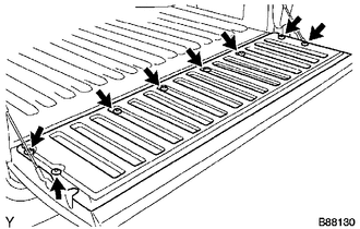
1. REMOVE TAIL GATE PROTECTOR
(See page .gif) )
)
2. REMOVE TAIL GATE SERVICE HOLE COVER
|
(a) Using a T30 "TORX" socket wrench, remove the 8 screws and tail gate service hole cover. |
|
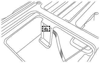
3. REMOVE REAR TELEVISION CAMERA ASSEMBLY
4. REMOVE TAIL GATE LOCK ASSEMBLY LH
|
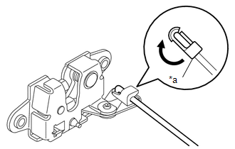
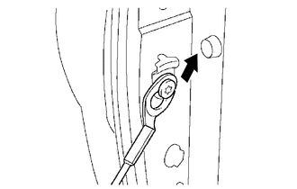
(a) Disconnect the snap and tail gate lock control link from the tail gate handle assembly as shown in the illustration. Text in Illustration
|
|
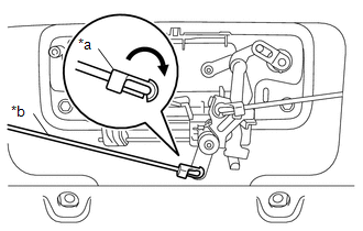
|
(b) Disengage the clamp. |
|
(c) Using a T40 "TORX" socket wrench, remove the 2 bolts and tail gate lock assembly LH.
5. REMOVE TAIL GATE LOCK ASSEMBLY RH
|
(a) Disconnect the snap and tail gate lock control link from the tail gate handle assembly as shown in the illustration. Text in Illustration
|
|
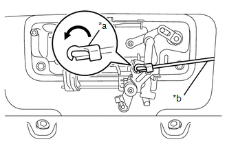
|
(b) Disengage the clamp. |
|
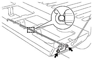
(c) Using a T40 "TORX" socket wrench, remove the 2 bolts and tail gate lock assembly RH.
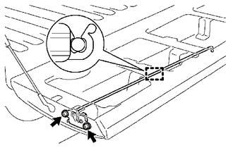
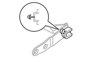
6. REMOVE TAIL GATE LOCK CONTROL LINK
|
(a) Disconnect the snap to remove the tail gate lock control link from the tail gate lock assembly LH as shown in the illustration. Text in Illustration
HINT: Use the same procedure for the LH side and RH side. |
|
7. REMOVE TAIL GATE HANDLE ASSEMBLY
|
(a) Remove the 2 bolts. |
|
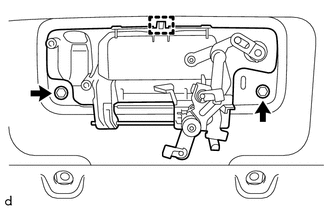
(b) Disengage the guide to remove the tail gate handle assembly.
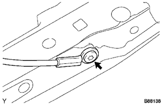
8. REMOVE TAIL GATE LOCK STRIKER
|
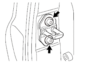
(a) Using a T40 "TORX" socket wrench, remove the 2 bolts and tail gate lock striker. HINT: Use the same procedure for the LH side and RH side. |
|
9. REMOVE TAIL GATE
|
(a) Disengage the clamp. |
|
|
(b) Disengage the clamp. |
|
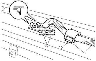
(c) Disengage the 2 claws and 2 guides to disconnect the wire harness from the tail gate.
Text in Illustration|
*a |
Guide |
|
*b |
Clamp |
|
(d) Disengage the tail gate stay from the tail gate stay stopper as shown in the illustration. HINT: Use the same procedure for the LH side and RH side. |
|
|
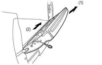
(e) Remove the tail gate from the vehicle in the order shown in the illustration. NOTICE: Be careful not to drop the tail gate. HINT: Remove the tail gate from the vehicle by lifting up the right side and sliding it slightly to the right. |
|
10. REMOVE TAIL GATE STAY STOPPER
|
(a) Using a T40 "TORX" socket wrench, remove the tail gate stay shaft and tail gate stopper. HINT: Use the same procedure for the LH side and RH side. |
|
11. REMOVE TAIL GATE STAY ASSEMBLY
|
(a) Using a T40 "TORX" socket wrench, remove the tail gate stay shaft, washer and tail gate stay assembly. HINT: Use the same procedure for the LH side and RH side. |
|
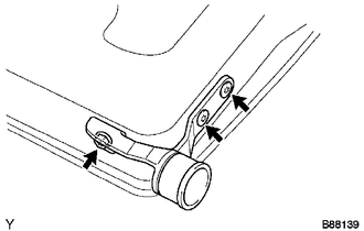
12. REMOVE TAIL GATE HINGE ASSEMBLY LH
|
(a) Using a T40 "TORX" socket wrench, remove the bolt, 2 screws and tail gate hinge assembly LH. |
|
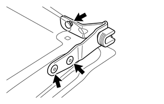
13. REMOVE TAIL GATE HINGE ASSEMBLY RH
|
(a) Using a T40 "TORX" socket wrench, remove the bolt, 2 screws and tail gate hinge assembly RH. |
|
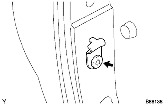
14. REMOVE SIDE GATE SUPPORT FEMALE HINGE RH
|
(a) Disengage the claw to remove the side gate support female hinge RH. |
|
15. REMOVE NO. 2 REAR BODY NAME PLATE (for 4WD)
16. REMOVE NO. 3 REAR BODY NAME PLATE (for 2GR-FKS)
 Components
COMPONENTS
ILLUSTRATION
ILLUSTRATION
ILLUSTRATION
...
 Reassembly
REASSEMBLY
PROCEDURE
1. INSTALL NO. 3 REAR BODY NAME PLATE (for 2GR-FKS)
2. INSTALL NO. 2 REAR BODY NAME PLATE (for 4WD)
3. INSTALL SIDE GATE SUPPORT FEMALE HINGE RH
(a) Engage ...
Other materials:
Removal
REMOVAL
PROCEDURE
1. REMOVE FRONT DOOR SCUFF PLATE LH (for Double Cab)
2. REMOVE FRONT DOOR SCUFF PLATE LH (for Access Cab)
3. REMOVE COWL SIDE TRIM BOARD LH
4. REMOVE INSTRUMENT CLUSTER CENTER FINISH PANEL SUB-ASSEMBLY
5. REMOVE INSTRUMENT CLUSTER FINISH PANEL ASSEMBLY
6. ...
Removal
REMOVAL
PROCEDURE
1. REMOVE FUEL DELIVERY PIPE ASSEMBLY LH (FUEL PRESSURE SENSOR)
(See page )
NOTICE:
Do not remove the fuel pressure sensor from the fuel delivery pipe sub-assembly
LH.
If a fuel pressure sensor is removed, replace the fuel delivery pipe
sub-assembly LH (fu ...
Customize Parameters
CUSTOMIZE PARAMETERS
1. CUSTOMIZE SMART KEY SYSTEM (for Entry Function)
HINT:
The following items can be customized.
NOTICE:
When the customer requests a change in a function, first make sure that
the function can be customized.
Record the current settings before customizing.
...
