Toyota Tacoma (2015-2018) Service Manual: Reassembly
REASSEMBLY
PROCEDURE
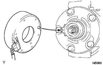
1. INSTALL COMPRESSOR PICK UP SENSOR
|
(a) Install the compressor pick up sensor with the 3 screws. |
|
.png)
(b) Engage the clamp.
2. INSTALL MAGNET CLUTCH ASSEMBLY
(a) Secure the cooler compressor assembly in a vise between aluminum plates.
(b) Install the magnet clutch stator with the parts shown in the illustration.
|
(c) Using a snap ring expander, install a new snap ring with the chamfered side facing up. |
|
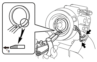
(d) Connect the connector.
(e) Install the screw.
|
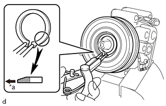
(f) Using a snap ring expander, install the magnet clutch rotor and a new snap ring with the chamfered side facing up. Text in Illustration
NOTICE: Do not damage the seal cover of the bearing when installing the snap ring. |
|
(g) Install the compressor spacer and magnet clutch hub.
NOTICE:
Do not change the combination of the compressor spacer used before disassembly.
|
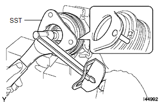
(h) Using SST, hold the magnet clutch hub and install the bolt. SST: 09985-00260 Torque: 13.5 N·m {138 kgf·cm, 10 ft·lbf} NOTICE: Make sure that there is no foreign matter or oil on the compressor shaft, bolt, and clutch hub. |
|
3. INSTALL PRESSURE RELIEF VALVE
(a) Apply sufficient compressor oil to a new O-ring and fitting surface of the pressure relief valve.
Compressor oil:
PSD1 or equivalent
(b) Install a new O-ring onto the pressure relief valve.
(c) Install the pressure relief valve.
Torque:
8.0 N·m {82 kgf·cm, 71 in·lbf}
4. INSPECT MAGNET CLUTCH CLEARANCE
|
(a) Secure the cooler compressor assembly in a vise between aluminum plates. Text in Illustration
|
|
(b) Set the dial indicator to the magnet clutch hub.
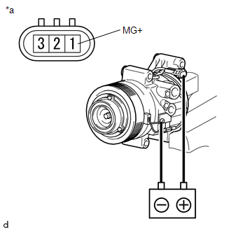
(c) Connect the battery positive lead to terminal 1 (MG+) of the magnet clutch connector and the negative lead to the ground wire. Turn the magnet clutch on and off and measure the clearance.
Standard clearance:
0.30 to 0.60 mm (0.012 to 0.024 in.)
If the measured value is not within the standard clearance, remove the magnet clutch hub and adjust the clearance using compressor spacer to obtain the standard clearance.
Compressor spacer thickness:
0.2 mm (0.008 in.)
0.3 mm (0.012 in.)
0.5 mm (0.020 in.)
NOTICE:
Adjustment should be performed with 3 or less magnet clutch washers.
(d) Remove the compressor and magnetic clutch from the vise.
 Inspection
INSPECTION
PROCEDURE
1. INSPECT MAGNET CLUTCH ASSEMBLY
(a) Inspect the magnet clutch assembly.
Text in Illustration
*a
Component without harness c ...
 Installation
INSTALLATION
PROCEDURE
1. ADJUST COMPRESSOR OIL
(a) for HFC-134a (R134a):
(1) When replacing the compressor and magnetic clutch with new ones, after gradually
discharging the refrigerant gas fro ...
Other materials:
Disassembly
DISASSEMBLY
PROCEDURE
1. REMOVE FRONT LICENSE PLATE BRACKET
(a) Remove the 2 screws and front license plate bracket.
2. REMOVE NO. 4 ENGINE ROOM WIRE (w/ Fog Light)
(a) Disconnect the 2 connectors.
...
Rear Power Outlet Switch
Components
COMPONENTS
ILLUSTRATION
Inspection
INSPECTION
PROCEDURE
1. INSPECT MAIN SWITCH ASSEMBLY
(a) Check the main switch assembly.
(1) Measure the resistance according to the value(s) in the table below.
Text in Illustration
*a
Com ...
Security Indicator Light Does not Blink
DESCRIPTION
The transponder key ECU assembly blinks the security indicator light
when the immobiliser is set (no key is in the ignition key cylinder).
w/ Theft Deterrent System:
The main body ECU (multiplex network body ECU) blinks the security indicator
light when the thef ...
