Toyota Tacoma (2015-2018) Service Manual: Rear Shock Absorber
Components
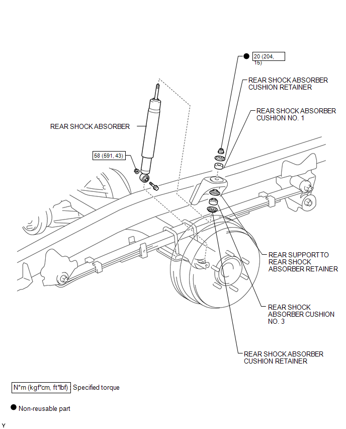
COMPONENTS
ILLUSTRATION
Inspection
INSPECTION
PROCEDURE
1. INSPECT REAR SHOCK ABSORBER
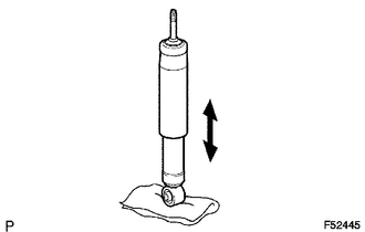
(a) Compress and extend the shock absorber rod and check that there is no abnormal resistance or abnormal sounds during operation.
If there is any abnormality, replace the shock absorber with a new one.
NOTICE:
When disposing of the shock absorber, see DISPOSAL on page
.gif) .
.
Removal
REMOVAL
PROCEDURE
1. REMOVE REAR WHEEL
2. REMOVE REAR SHOCK ABSORBER
.png)
(a) Support the rear axle housing.
(b) Remove the bolt, nut and washer.
(c) Separate the shock absorber from the rear axle housing.
|
(d) Remove the nut, 3 cushion retainers, cushion No. 1, cushion No. 3 and shock absorber. |
|
Disposal
DISPOSAL
PROCEDURE
1. DISPOSE OF REAR SHOCK ABSORBER
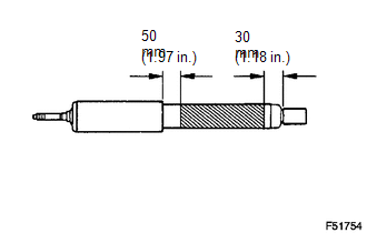
(a) Fully extend the shock absorber rod.
(b) Using a drill, make a hole in the shaded area of the cylinder as shown in the illustration, to discharge the gas inside.
CAUTION:
- Be careful when drilling because shards of metal may scatter.
- The gas is colorless, odorless and non-poisonous.
Installation
INSTALLATION
PROCEDURE
1. INSTALL REAR SHOCK ABSORBER
.png)
(a) Install the 3 cushion retainers, cushion No. 1, cushion No. 3 and shock absorber with a new nut.
|
(b) Install the shock absorber with the bolt, nut and washer. |
|
|
(c) Fully tighten the nut. Torque: 20 N·m {204 kgf·cm, 15 ft·lbf} |
|
2. INSTALL REAR WHEEL
Torque:
113 N·m {1152 kgf·cm, 83 ft·lbf}
3. STABILIZE SUSPENSION
(a) Jack down the vehicle.
(b) Bounce the vehicle up and down several times to stabilize the suspension.
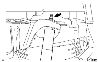
4. FULLY TIGHTEN REAR SHOCK ABSORBER
.png)
(a) Fully tighten the nut.
Torque:
58 N·m {591 kgf·cm, 43 ft·lbf}
 Rear Leaf Spring
Components
COMPONENTS
ILLUSTRATION
Disassembly
DISASSEMBLY
PROCEDURE
1. REMOVE BUSH
(a) Fix the spring in a vise.
(b) Using a hack saw, cut both ends off the bushes.
(c) Us ...

Other materials:
Evaporator Temperature Sensor Circuit (B1413)
DESCRIPTION
The cooler thermistor sensor (evaporator temperature sensor) is installed on
the evaporator in the air conditioner unit to detect the temperature of the cooled
air that has passed through the evaporator and is used to control the air conditioning.
It sends signals to the air condi ...
Diagnosis System
DIAGNOSIS SYSTEM
1. DESCRIPTION
The 4 wheel drive control ECU records DTCs when the ECU detects a malfunction
in the ECU itself or in system circuits.
The DTCs can be read through the DLC3 of the vehicle. When the system seems to
be malfunctioning, use the Techstream to check for malfunctions ...
Rear Combination Light Assembly
Components
COMPONENTS
ILLUSTRATION
Disassembly
DISASSEMBLY
CAUTION / NOTICE / HINT
HINT:
Use the same procedure for both the LH and RH sides.
The procedure described below is for the LH side.
PROCEDURE
1. REMOVE TAIL AND TURN SIGNAL LIGHT BULB
(a) Turn th ...
