Toyota Tacoma (2015-2018) Service Manual: Rear Differential Lock Position SW Stuck ON (P17BC)
DESCRIPTION
This DTC is output when an ON malfunction of the differential lock indicator switch is detected.
|
DTC No. |
Detection Item |
DTC Detection Condition |
Trouble Area |
|---|---|---|---|
|
P17BC |
Rear Differential Lock Position SW Stuck ON |
|
|
WIRING DIAGRAM
Refer to DTC P17BB (See page .gif) ).
).
PROCEDURE
|
1. |
CHECK HARNESS AND CONNECTOR (4 WHEEL DRIVE CONTROL ECU - DIFFERENTIAL LOCK INDICATOR SWITCH) |
(a) Disconnect the F13 4 wheel drive control ECU connector.
(b) Disconnect the T13 differential lock indicator switch connector.
(c) Measure the resistance according to the value(s) in the table below.
Standard Resistance:
|
Tester Connection |
Condition |
Specified Condition |
|---|---|---|
|
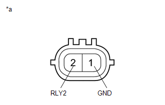
F13-12 (SLS) or T13-2 (RLY2) - Body ground |
Always |
10 kΩ or higher |
| NG | .gif) |
REPAIR OR REPLACE HARNESS OR CONNECTOR |
|
.gif)
|
2. |
INSPECT DIFFERENTIAL LOCK INDICATOR SWITCH |
(a) for Automatic Transmission:
Move the shift lever to N.
for Manual Transmission:
Move the shift lever to neutral.
(b) for 4WD:
Switch the transfer position switch to L4.
(c) Lift up the vehicle until all four wheels are off the ground.
(d) Release the parking brake.
(e) Rotate one rear wheel and set the rear differential to the free condition.
(f) Disconnect the T13 differential lock indicator switch connector.
|
(g) Measure the resistance according to the value(s) in the table below. Standard Resistance:
|
|
| OK | |
REPLACE 4 WHEEL DRIVE CONTROL ECU |
| NG | |
REPLACE DIFFERENTIAL LOCK INDICATOR SWITCH |
 Rear Differential Lock Position SW Stuck OFF (P17BB)
DESCRIPTION
This DTC is output when an OFF malfunction of the differential lock indicator
switch is detected.
DTC No.
Detection Item
DTC Detection Condition
...
 4WD ECU Malfunction (P163B)
DESCRIPTION
This DTC is output when a malfunction is detected in the 4 wheel drive control
ECU internal circuit.
DTC No.
Detection Item
DTC Detection Condition
...
Other materials:
On-vehicle Inspection
ON-VEHICLE INSPECTION
PROCEDURE
1. INSPECT ENGINE COOLANT
(See page )
2. INSPECT ENGINE OIL
(See page )
3. INSPECT BATTERY
(See page )
4. INSPECT SPARK PLUG
(See page )
5. INSPECT AIR CLEANER FILTER ELEMENT SUB-ASSEMBLY
(a) Remove the air cleaner filter element sub-assembly.
(b) Visu ...
AV Signal Stoppage (Low Battery Voltage) (B158F)
DESCRIPTION
This DTC is stored when a video or audio signal is interrupted due to battery
voltage input to the radio and display receiver assembly dropping temporarily.
DTC Code
DTC Detection Condition
Trouble Area
B158F
A video or aud ...
Daytime Running Light Relay Circuit
DESCRIPTION
The main body ECU (multiplex network body ECU) controls the daytime running lights.
WIRING DIAGRAM
CAUTION / NOTICE / HINT
NOTICE:
Inspect the fuses for circuits related to this system before performing
the following inspection procedure.
If the main body ECU (mult ...
