Toyota Tacoma (2015-2018) Service Manual: 4WD ECU Malfunction (P163B)
DESCRIPTION
This DTC is output when a malfunction is detected in the 4 wheel drive control ECU internal circuit.
|
DTC No. |
Detection Item |
DTC Detection Condition |
Trouble Area |
|---|---|---|---|
|
P163B |
4WD ECU Malfunction |
|
|
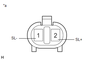
WIRING DIAGRAM
.png)
CAUTION / NOTICE / HINT
NOTICE:
4WD specification:
- If P163B is detected, troubleshoot the TOUCH SELECT 2-4 AND HIGH-LOW system first.
PROCEDURE
|
1. |
CHECK HARNESS AND CONNECTOR (4 WHEEL DRIVE CONTROL ECU - DIFFERENTIAL LOCK COIL) |
(a) Turn the ignition switch off.
(b) Disconnect the F12 4 wheel drive control ECU connector.
(c) Disconnect the D28 differential lock coil connector.
(d) Measure the resistance according to the value(s) in the table below.
Standard Resistance:
|
Tester Connection |
Condition |
Specified Condition |
|---|---|---|
|
F12-1 (SL+) - D28-2 (SL+) |
Always |
Below 1 Ω |
|
F12-5 (SL-) - D28-1 (SL-) |
Always |
Below 1 Ω |
|
F12-1 (SL+) or D28-2 (SL+) - Body ground |
Always |
10 kΩ or higher |
|
F12-5 (SL-) or D28-1 (SL-) - Body ground |
Always |
10 kΩ or higher |
(e) Measure the voltage according to the value(s) in the table below.
Standard Voltage:
|
Tester Connection |
Switch Condition |
Specified Condition |
|---|---|---|
|
F12-1 (SL+) or D28-2 (SL+) - Body ground |
Ignition switch ON |
Below 1 V |
|
F12-5 (SL-) or D28-1 (SL-) - Body ground |
Ignition switch ON |
Below 1 V |
| NG | .gif) |
REPAIR OR REPLACE HARNESS AND CONNECTOR |
|
.gif)
|
2. |
INSPECT DIFFERENTIAL LOCK COIL |
(a) Turn the ignition switch off.
(b) Disconnect the D28 differential lock coil connector.
|
(c) Measure the resistance according to the value(s) in the table below. Standard Resistance:
|
|
(d) Measure the voltage according to the value(s) in the table below.
Standard Voltage:
|
Tester Connection |
Switch Condition |
Specified Condition |
|---|---|---|
|
1 (SL-) or 2 (SL+) - Body ground |
Ignition switch ON |
Below 1 V |
| OK | |
REPLACE 4 WHEEL DRIVE CONTROL ECU |
| NG | |
REPLACE DIFFERENTIAL LOCK COIL |
 Rear Differential Lock Position SW Stuck ON (P17BC)
DESCRIPTION
This DTC is output when an ON malfunction of the differential lock indicator
switch is detected.
DTC No.
Detection Item
DTC Detection Condition
...
 ECU Power Source Circuit
WIRING DIAGRAM
CAUTION / NOTICE / HINT
NOTICE:
Inspect the fuses for circuits related to this system before performing the following
inspection procedure.
PROCEDURE
1.
...
Other materials:
Problem Symptoms Table
PROBLEM SYMPTOMS TABLE
NOTICE:
After replacing the stereo component tuner assembly of vehicles subscribed to
pay-type satellite radio broadcasts, XM radio ID registration is necessary (w/ SDARS
System).
HINT:
Use the table below to help determine the cause of problem symptoms.
If ...
Removal
REMOVAL
CAUTION / NOTICE / HINT
NOTICE:
Release the vacuum from booster by depressing the brake pedal several times.
Then remove the brake master cylinder from brake booster.
PROCEDURE
1. PRECAUTION
NOTICE:
After turning the ignition switch off, waiting time may be required before disconnect ...
FCM Destination Information Uninitialized (C1AAA)
DESCRIPTION
When the forward recognition camera is replaced with a new one, the new forward
recognition camera attempts to store the country specification information received
from the main body ECU (multiplex network body ECU). If the forward recognition
camera cannot store the country speci ...
