Toyota Tacoma (2015-2018) Service Manual: Rear Differential Lock Position SW Stuck OFF (P17BB)
DESCRIPTION
This DTC is output when an OFF malfunction of the differential lock indicator switch is detected.
|
DTC No. |
Detection Item |
DTC Detection Condition |
Trouble Area |
|---|---|---|---|
|
P17BB |
Rear Differential Lock Position SW Stuck OFF |
|
|
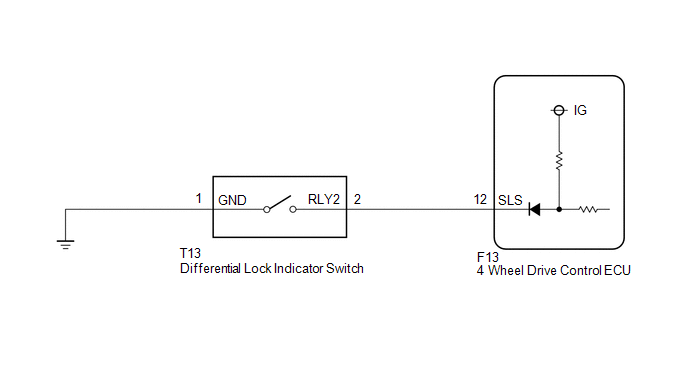
WIRING DIAGRAM
CAUTION / NOTICE / HINT
HINT:
for 4WD:
When the rear differential lock position switch (transfer indicator switch) is stuck OFF, if the transfer is set to 2WD, the vehicle is stopped and the ignition switch is turned from off to ON, the system returns to normal and this DTC is stored as a past DTC.
If the transfer is set to L4 again, the rear differential is locked and the vehicle is driven at 5 km/h or more, this DTC is output again.
for 2WD:
When the rear differential lock position switch (transfer indicator switch) is stuck OFF, the vehicle is stopped and the ignition switch is turned from off to ON, the system returns to normal and this DTC is stored as a past DTC.
If the rear differential is locked and the vehicle is driven at 5 km/h or more, this DTC is output again.
PROCEDURE
|
1. |
CHECK HARNESS AND CONNECTOR (4 WHEEL DRIVE CONTROL ECU - DIFFERENTIAL LOCK INDICATOR SWITCH) |
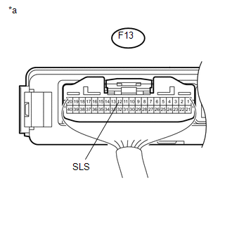
(a) Disconnect the F13 4 wheel drive control ECU connector.
(b) Disconnect the T13 differential lock indicator switch connector.
(c) Measure the resistance according to the value(s) in the table below.
Standard Resistance:
|
Tester Connection |
Condition |
Specified Condition |
|---|---|---|
|
F13-12 (SLS) - T13-2 (RLY2) |
Always |
Below 1 Ω |
|
T13-1 (GND) - Body ground |
Always |
Below 1 Ω |
| NG | .gif) |
REPAIR OR REPLACE HARNESS OR CONNECTOR |
|
.gif)
|
2. |
CHECK 4 WHEEL DRIVE CONTROL ECU (ECU OUTPUT VOLTAGE) |
|
(a) Disconnect the differential lock indicator switch connector. |
|
(b) Measure the voltage according to the value(s) in the table below.
Standard Voltage:
|
Tester Connection |
Switch Condition |
Specified Condition |
|---|---|---|
|
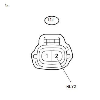
T13-2 (RLY2) - Body ground |
Ignition switch ON |
10 to 14 V |
|
*a |
Front view of wire harness connector (to Differential Lock Indicator Switch) |
| NG | |
REPLACE 4 WHEEL DRIVE CONTROL ECU |
|
|
3. |
CHECK DIFFERENTIAL LOCK INDICATOR SWITCH |
(a) for Automatic Transmission:
Move the shift lever to N.
for Manual Transmission:
Move the shift lever to neutral.
(b) for 4WD:
Switch the transfer position switch to L4.
(c) Lift up the vehicle until all four wheels are off the ground.
(d) Release the parking brake.
(e) Operate the differential lock switch to switch to locked.
HINT:
The rear differential lock indicator light continues to blink.
(f) Rotate one rear wheel in both directions and set the rear differential to the locked condition.
HINT:
When the rear differential is locked, rotating one rear wheel causes the other rear wheel to rotate in the same direction.
|
(g) Measure the voltage according to the value(s) in the table below. Standard Voltage:
|
|
| OK | |
REPLACE 4 WHEEL DRIVE CONTROL ECU |
| NG | |
REPLACE DIFFERENTIAL LOCK INDICATOR SWITCH |
 Rear Differential Lock Control SW Stuck ON (P17CC)
DESCRIPTION
This DTC is output when a malfunction of the differential lock switch is detected.
DTC No.
Detection Item
DTC Detection Condition
Trouble Area ...
 Rear Differential Lock Position SW Stuck ON (P17BC)
DESCRIPTION
This DTC is output when an ON malfunction of the differential lock indicator
switch is detected.
DTC No.
Detection Item
DTC Detection Condition
...
Other materials:
Inspection
INSPECTION
PROCEDURE
1. REMOVE SPIRAL CABLE SUB-ASSEMBLY WITH SENSOR
(a) If there are any defects as mentioned below, replace the spiral cable sub-assembly
with a new one:
Scratches, cracks, dents or chips on the connector or the spiral cable sub-assembly.
(b) Inspect the spiral ca ...
Dtc Check / Clear
DTC CHECK / CLEAR
CHECK DTC
(a) Connect the Techstream to the DLC3.
(b) Turn the ignition switch to ON.
(c) Turn the Techstream on.
(d) Enter the following menus: Chassis / Front Recognition Camera / Trouble Codes.
(e) Check for details of the DTCs.
Click here
CLEAR DTC
(a) Connect the Te ...
Road Test
ROAD TEST
PROBLEM SYMPTOM CONFIRMATION
HINT:
The dynamic radar cruise control system has 2 cruise control modes:
constant speed control mode and vehicle-to-vehicle distance control mode.
Vehicle-to-vehicle distance control mode is selected by default when
the dyna ...
