Toyota Tacoma (2015-2018) Service Manual: Stereo Component Amplifier Power Source Circuit
DESCRIPTION
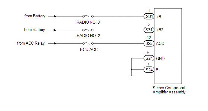
This circuit provides power to the stereo component amplifier assembly.
WIRING DIAGRAM
CAUTION / NOTICE / HINT
Inspect the fuses for circuits related to this system before performing the following inspection procedure.
PROCEDURE
|
1. |
CHECK HARNESS AND CONNECTOR (STEREO COMPONENT AMPLIFIER ASSEMBLY POWER SOURCE) |
|
(a) Disconnect the stereo component amplifier assembly connectors. |
|
(b) Measure the resistance according to the value(s) in the table below.
Standard Resistance:
|
Tester Connection |
Condition |
Specified Condition |
|---|---|---|
|
S24-6 (GND) - Body ground |
Always |
Below 1 Ω |
|
S24-7 (E) - Body ground |
Always |
Below 1 Ω |
(c) Measure the voltage according to the value(s) in the table below.
Standard Voltage:
|
Tester Connection |
Switch Condition |
Specified Condition |
|---|---|---|
|
S31-1 (+B) - S24-6 (GND) |
Always |
11 to 14 V |
|
S31-5 (+B2) - S24-6 (GND) |
Always |
11 to 14 V |
|
S23-12 (ACC) - S24-6 (GND) |
Ignition switch ACC |
11 to 14 V |
|
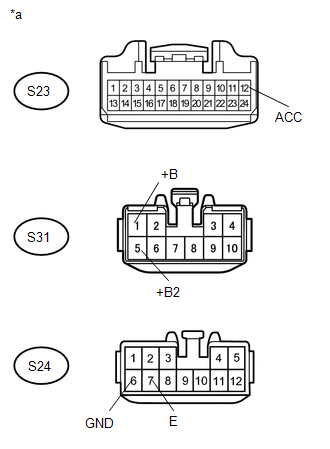
*a |
Front view of wire harness connector (to Stereo Component Amplifier Assembly) |
| OK | .gif) |
PROCEED TO NEXT SUSPECTED AREA SHOWN IN PROBLEM SYMPTOMS TABLE |
| NG | |
REPAIR OR REPLACE HARNESS AND CONNECTOR |
 Radio Receiver Power Source Circuit
DESCRIPTION
This is the power source circuit to operate the navigation receiver assembly.
WIRING DIAGRAM
CAUTION / NOTICE / HINT
NOTICE:
Inspect the fuses for circuits related to this s ...

Other materials:
Installation
INSTALLATION
PROCEDURE
1. INSTALL PROPELLER SHAFT WITH CENTER BEARING ASSEMBLY
(a) Remove SST from the extension housing.
(b) Install the propeller shaft to the extension housing.
(c) Completely remove any oil or the like and clean the contact surfaces of the
propeller shaft flange and diff ...
Reassembly
REASSEMBLY
CAUTION / NOTICE / HINT
HINT:
Use the same procedure for both the LH and RH sides.
The procedure described below is for the LH side.
PROCEDURE
1. INSTALL FOG LIGHT BULB
(a) Turn the fog light bulb in the direction indicated by the arrow in
the illust ...
Fuel information
Your vehicle must use only unleaded gasoline.
Select octane rating 87 (Research Octane Number 91) or higher. Use of unleaded
gasoline with an octane rating lower than 87 may result in engine knocking. Persistent
knocking can lead to engine damage.
At minimum, the gasoline you use should meet t ...
