Toyota Tacoma (2015-2018) Service Manual: PTC Heater Circuit
DESCRIPTION
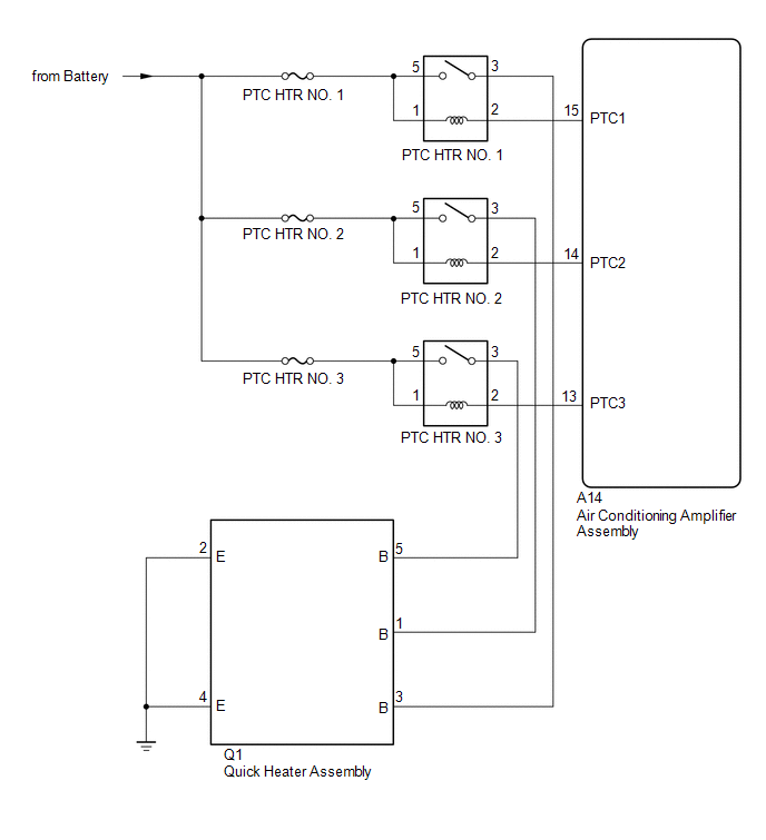
PTC HTR heater relays are closed in accordance with signals from the air conditioning amplifier assembly and power is supplied to the quick heater assembly installed on the radiator heater unit.
WIRING DIAGRAM
CAUTION / NOTICE / HINT
NOTICE:
Inspect the fuses for circuits related to this system before performing the following inspection procedure.
PROCEDURE
|
1. |
PERFORM ACTIVE TEST USING TECHSTREAM |
(a) Connect the Techstream to the DLC3.
(b) Turn the ignition switch to ON.
(c) Turn the Techstream on.
(d) Enter the following menus: Body Electrical / Air Conditioner / Active Test.
(e) Check the operation by referring to the table below.
Air Conditioner|
Tester Display |
Test Part |
Control Range |
Diagnostic Note |
|---|---|---|---|
|
Heater Active Level |
Quick heater assembly |
Min.: 0, Max.: 3 |
- |
OK:
Heater Active Level changes normally.
| NG | .gif) |
PROCEED TO NEXT SUSPECTED AREA SHOWN IN PROBLEM SYMPTOMS TABLE |
|
.gif)
|
2. |
INSPECT PTC HTR RELAY |
(a) Remove the PTC HTR relays.
(b) Inspect the PTC HTR relays (See page .gif) ).
).
| NG | |
REPLACE PTC HTR RELAY |
|
|
3. |
CHECK HARNESS AND CONNECTOR (PTC HTR RELAY - POWER SOURCE CIRCUIT) |
(a) Remove the PTC HTR relays.
(b) Measure the voltage according to the value(s) in the table below.
Standard Voltage:
PTC HTR NO. 1|
Tester Connection |
Condition |
Specified Condition |
|---|---|---|
|
PTC HTR NO. 1-1 - Body ground |
Always |
11 to 14 V |
|
PTC HTR NO. 1-5 - Body ground |
Always |
11 to 14 V |
|
Tester Connection |
Condition |
Specified Condition |
|---|---|---|
|
PTC HTR NO. 2-1 - Body ground |
Always |
11 to 14 V |
|
PTC HTR NO. 2-5 - Body ground |
Always |
11 to 14 V |
|
Tester Connection |
Condition |
Specified Condition |
|---|---|---|
|
PTC HTR NO. 3-1 - Body ground |
Always |
11 to 14 V |
|
PTC HTR NO. 3-5 - Body ground |
Always |
11 to 14 V |
| NG | |
REPAIR OR REPLACE HARNESS OR CONNECTOR |
|
|
4. |
CHECK HARNESS AND CONNECTOR (PTC HTR RELAY - AIR CONDITIONING AMPLIFIER ASSEMBLY) |
(a) Remove the PTC HTR relays.
(b) Disconnect the A14 air conditioning amplifier assembly connector.
(c) Measure the resistance according to the value(s) in the table below.
Standard Resistance:
PTC HTR NO. 1|
Tester Connection |
Condition |
Specified Condition |
|---|---|---|
|
PTC HTR NO. 1-2 - A14-15 (PTC1) |
Always |
Below 1 Ω |
|
PTC HTR NO. 1-2 or A14-15 (PTC1) - Body ground |
Always |
10 kΩ or higher |
|
Tester Connection |
Condition |
Specified Condition |
|---|---|---|
|
PTC HTR NO. 2-2 - A14-14 (PTC2) |
Always |
Below 1 Ω |
|
PTC HTR NO. 2-2 or A14-14 (PTC2) - Body ground |
Always |
10 kΩ or higher |
|
Tester Connection |
Condition |
Specified Condition |
|---|---|---|
|
PTC HTR NO. 3-2 - A14-13 (PTC3) |
Always |
Below 1 Ω |
|
PTC HTR NO. 3-2 or A14-13 (PTC3) - Body ground |
Always |
10 kΩ or higher |
| NG | |
REPAIR OR REPLACE HARNESS OR CONNECTOR |
|
|
5. |
CHECK HARNESS AND CONNECTOR (QUICK HEATER ASSEMBLY - PTC HTR RELAY AND BODY GROUND) |
(a) Remove the PTC HTR relays.
(b) Disconnect the Q1 quick heater assembly connector.
(c) Measure the resistance according to the value(s) in the table below.
Standard Resistance:
PTC HTR NO. 1|
Tester Connection |
Condition |
Specified Condition |
|---|---|---|
|
PTC HTR NO. 1-3 - Q1-3 (B) |
Always |
Below 1 Ω |
|
Q1-2 (E) - Body ground |
Always |
Below 1 Ω |
|
Q1-4 (E) - Body ground |
Always |
Below 1 Ω |
|
PTC HTR NO. 1-3 or Q1-3 (B) - Body ground |
Always |
10 kΩ or higher |
|
Tester Connection |
Condition |
Specified Condition |
|---|---|---|
|
PTC HTR NO. 2-3 - Q1-1 (B) |
Always |
Below 1 Ω |
|
Q1-2 (E) - Body ground |
Always |
Below 1 Ω |
|
PTC HTR NO. 2-3 or Q1-1 (B) - Body ground |
Always |
10 kΩ or higher |
|
Tester Connection |
Condition |
Specified Condition |
|---|---|---|
|
PTC HTR NO. 3-3 - Q1-5 (B) |
Always |
Below 1 Ω |
|
Q1-4 (E) - Body ground |
Always |
Below 1 Ω |
|
PTC HTR NO. 3-3 or Q1-5 (B) - Body ground |
Always |
10 kΩ or higher |
| NG | |
REPAIR OR REPLACE HARNESS OR CONNECTOR |
|
|
6. |
INSPECT QUICK HEATER ASSEMBLY |
(a) Remove the quick heater assembly (See page
).
(b) Inspect the quick heater assembly (See page
).
| OK | |
REPLACE AIR CONDITIONING AMPLIFIER ASSEMBLY |
| NG | |
REPLACE QUICK HEATER ASSEMBLY |
 Compressor Lock Sensor Circuit (B1422)
SYSTEM DESCRIPTION
The ECM sends the engine speed signal to the air conditioning amplifier assembly
via CAN communication.
The air conditioning amplifier assembly reads the difference between comp ...

Other materials:
Jam Protection Function does not Operate
DESCRIPTION
This symptom may occur for any of the windows.
The jam protection function operates within a specified range during the manual
up or auto up operation.
CAUTION / NOTICE / HINT
NOTICE:
If a power window regulator motor assembly has been replaced with a
new one, initiali ...
Operation Check
OPERATION CHECK
1. CHECK WINDOW LOCK SWITCH
HINT:
Before performing the window lock switch operation check, make sure that the
window lock switch is off (the switch is not pushed in).
(a) Check that the front passenger and rear windows cannot be operated from each
power window regulator swit ...
IG Signal Circuit
DESCRIPTION
This circuit detects whether the ignition switch is ON or off, and sends this
information to the main body ECU (multiplex network body ECU).
WIRING DIAGRAM
CAUTION / NOTICE / HINT
NOTICE:
Inspect the fuses for circuits related to this system before performing
the fol ...
