Toyota Tacoma (2015-2018) Service Manual: Power Source Mode does not Change to ON (IG)
DESCRIPTION
If the engine switch is pressed with the electrical key transmitter sub-assembly in the cabin, the certification ECU (smart key ECU assembly) receives a signal and changes the power source mode.
HINT:
When the cable is disconnected and reconnected to the negative (-) battery terminal, the power source mode returns to the state it was in before the cable was disconnected.
WIRING DIAGRAM
Refer to Power Source Mode does not Change to ON (IG and ACC) (See page
.gif) ).
).
CAUTION / NOTICE / HINT
NOTICE:
- When using the Techstream with the engine switch off, connect the Techstream to the DLC3 and turn a courtesy light switch on and off at intervals of 1.5 seconds or less until communication between the Techstream and the vehicle begins. Then select the vehicle type under manual mode and enter the following menus: Body Electrical / Smart Key. While using the Techstream, periodically turn a courtesy light switch on and off an intervals of 1.5 seconds or less to maintain communication between the Techstream and the vehicle.
- The smart key system (for Start Function) uses a multiplex communication
system (LIN communication system) and the CAN communication system. Inspect
the communication function by following How to Proceed with Troubleshooting.
Click here
Troubleshoot the smart key system (for Start Function) after confirming that the communication systems are functioning properly.
- Make sure that no DTCs are output. If any DTCs are output, proceed to
the Diagnostic Trouble Code Chart (See page
).
- If the smart key system is disabled through the customize function,
enable the system before performing troubleshooting (See page
).
- Before replacing the certification ECU (smart key ECU assembly), refer
to the smart key system (for Start Function) precaution (See page
).
- Inspect the fuses of circuits related to this system before performing the following inspection procedure.
- After completing repairs, confirm that the problem does not occur.
|
Problem Symptom |
Data List and Active Test |
|---|---|
|
Power source mode does not change to on (IG) but does change to on (ACC) |
Power Source Control
Starting Control
|
PROCEDURE
|
1. |
CHECK FOR DTC |
(a) Using the Techstream, check for certification ECU (smart key ECU assembly)
DTCs (See page ).
|
Result |
Proceed to |
|---|---|
|
DTCs are not output |
A |
|
Smart key system (for Start Function) DTCs are output |
B |
| B | .gif) |
GO TO DIAGNOSTIC TROUBLE CODE CHART |
|
.gif)
|
2. |
CHECK HARNESS AND CONNECTOR (CERTIFICATION ECU (SMART KEY ECU ASSEMBLY) - DRIVER SIDE JUNCTION BLOCK) |
(a) Disconnect the C27 certification ECU (smart key ECU assembly) connector.
(b) Disconnect the 1A and 1D driver side junction block connectors.
(c) Measure the resistance according to the value(s) in the table below.
Standard Resistance:
|
Tester Connection |
Condition |
Specified Condition |
|---|---|---|
|
C27-3 (IG1D) - 1A-16 |
Always |
Below 1 Ω |
|
1D-5 - Body ground |
Always |
Below 1 Ω |
|
C27-3 (IG1D) or 1D-5 - Body ground |
Always |
10 kΩ or higher |
| NG | |
REPAIR OR REPLACE HARNESS OR CONNECTOR |
|
|
3. |
CHECK HARNESS AND CONNECTOR (CERTIFICATION ECU (SMART KEY ECU ASSEMBLY) - IG2-MAIN RELAY) |
(a) Disconnect the C27 certification ECU (smart key ECU assembly) connector.
(b) Remove the IG2-MAIN relay from the engine room relay block.
(c) Disconnect the 1A driver side junction block connector.
(d) Measure the resistance according to the value(s) in the table below.
Standard Resistance:
|
Tester Connection |
Condition |
Specified Condition |
|---|---|---|
|
C27-3 (IG1D) - 1 (IG2-MAIN relay) |
Always |
Below 1 Ω |
|
2 (IG2-MAIN relay) - Body ground |
Always |
Below 1 Ω |
|
C27-3 (IG1D) or 1 (IG2-MAIN relay) - Body ground |
Always |
10 kΩ or higher |
| NG | |
REPAIR OR REPLACE HARNESS OR CONNECTOR |
|
|
4. |
CHECK DRIVER SIDE JUNCTION BLOCK (IG1 NO. 1, IG1 NO. 2, IG1 NO.3 RELAY) |
(a) Remove the driver side junction block (See page
).
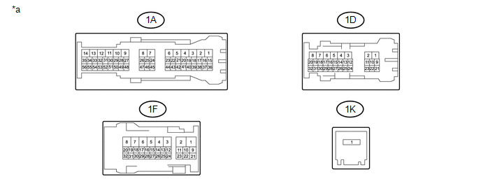 Text in Illustration
|
*a |
Component without harness connected (Driver Side Junction Block) |
- |
- |
(b) Measure the resistance according to the value(s) in the table below.
Standard Resistance:
|
Tester Connection |
Condition |
Specified Condition |
|---|---|---|
|
1A-16 - 1D-5 |
20°C (68°F) |
87.32 to 127.14 Ω |
|
1K-1 - 1F-1 |
Battery voltage applied to terminals 1A-16 and 1D-5 |
Below 1 Ω |
|
Battery voltage not applied to terminals 1A-16 and 1D-5 |
10 kΩ or higher |
|
|
1K-1 - 1D-4 |
Battery voltage applied to terminals 1A-16 and 1D-5 |
Below 1 Ω |
|
Battery voltage not applied to terminals 1A-16 and 1D-5 |
10 kΩ or higher |
|
|
1K-1 - 1F-12 |
Battery voltage applied to terminals 1A-16 and 1D-5 |
Below 1 Ω |
|
Battery voltage not applied to terminals 1A-16 and 1D-5 |
10 kΩ or higher |
| NG | |
REPLACE DRIVER SIDE JUNCTION BLOCK |
|
|
5. |
INSPECT IG2-MAIN RELAY |
|
(a) Remove the IG2-MAIN relay. |
|
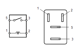
(b) Measure the resistance according to the value(s) in the table below.
Standard Resistance:
|
Tester Connection |
Condition |
Specified Condition |
|---|---|---|
|
3 - 5 |
Battery voltage applied to terminals 1 and 2 |
Below 1 Ω |
|
Battery voltage not applied to terminals 1 and 2 |
10 kΩ or higher |
|
*1 |
IG2-MAIN Relay |
| NG | |
REPLACE IG2-MAIN RELAY |
|
|
6. |
CHECK CERTIFICATION ECU (SMART KEY ECU ASSEMBLY) |
|
(a) Reconnect the certification ECU (smart key ECU assembly) connector. |
|
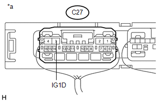
(b) Install the driver side junction block.
(c) Install the IG2-MAIN relay.
(d) Measure the voltage according to the value(s) in the table below.
Standard Voltage:
|
Tester Connection |
Condition |
Specified Condition |
|---|---|---|
|
C27-3 (IG1D) - Body ground |
Engine switch on (ACC) → Engine switch on (IG) |
1 V or less → 9 V or higher |
|
*a |
Component with harness connected (Certification ECU (Smart Key ECU Assembly)) |
| OK | |
USE SIMULATION METHOD TO CHECK |
| NG | |
REPLACE CERTIFICATION ECU (SMART KEY ECU ASSEMBLY) |
 Power Source Mode does not Change to ON (IG and ACC)
DESCRIPTION
If any of the following operations are performed, the certification ECU (smart
key ECU assembly) receives a signal, and changes the power source mode.
With the electrical key tr ...
 Power Source Mode does not Change to ON (ACC)
DESCRIPTION
If the engine switch is pressed with the electrical key transmitter sub-assembly
in the cabin, the certification ECU (smart key ECU assembly) receives a signal and
changes the power s ...
Other materials:
Clutch Release Cylinder(for R156f)
Components
COMPONENTS
ILLUSTRATION
Removal
REMOVAL
PROCEDURE
1. DRAIN CLUTCH FLUID
2. REMOVE FRONT PROPELLER SHAFT ASSEMBLY
(See page )
3. DISCONNECT CLUTCH RELEASE CYLINDER TO FLEXIBLE HOSE TUBE
(a) Using a union nut wrench, disconnect the clutch release cylinder
to ...
Output Shaft
Components
COMPONENTS
ILLUSTRATION
Disassembly
DISASSEMBLY
PROCEDURE
1. REMOVE FRONT OUTPUT SHAFT BEARING
(a) Temporarily install the manual transmission output shaft rear set
nut to the output shaft.
Text in Illustration
*1
Manual ...
SM Solenoid Circuit (C1225,C1468,C1469,C146A,C146B)
DESCRIPTION
These solenoids turn on when signals are received from the skid control ECU (brake
actuator assembly) and they control the pressure acting on the wheel cylinders to
control the braking force.
DTC No.
Detection Item
DTC Detection Condition
...
