Toyota Tacoma (2015-2018) Service Manual: Power Source Circuit
DESCRIPTION
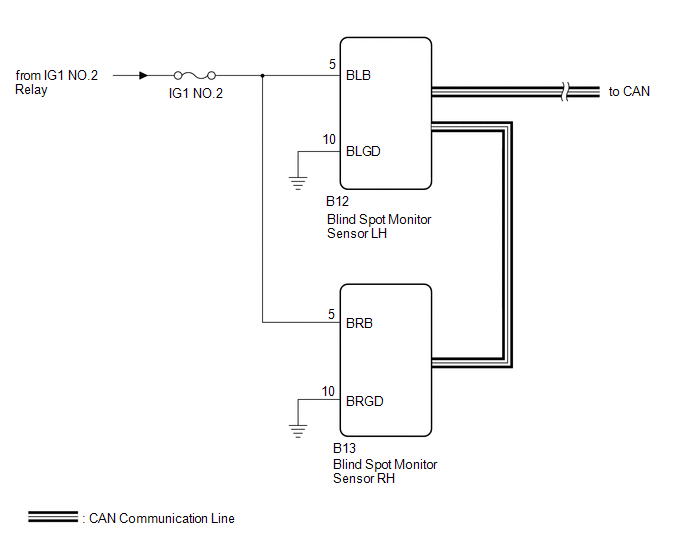
This circuit provides power to operate the blind spot monitor sensor.
WIRING DIAGRAM
CAUTION / NOTICE / HINT
NOTICE:
Inspect the fuses for circuits related to this system before performing the following inspection procedure.
PROCEDURE
|
1. |
CHECK HARNESS AND CONNECTOR (BLIND SPOT MONITOR SENSOR RH, BLIND SPOT MONITOR SENSOR LH - BATTERY AND BODY GROUND) |
|
(a) Disconnect the blind spot monitor sensor LH connector. |
|
(b) Disconnect the blind spot monitor sensor RH connector.
(c) Measure the voltage according to the value(s) in the table below.
Standard Voltage:
|
Tester Connection |
Switch Condition |
Specified Condition |
|---|---|---|
|
B12-5 (BLB) - Body ground |
Ignition switch ON |
11 to 14 V |
|
B12-5 (BLB) - Body ground |
Ignition switch off |
Below 1 V |
|
B13-5 (BRB) - Body ground |
Ignition switch ON |
11 to 14 V |
|
B13-5 (BRB) - Body ground |
Ignition switch off |
Below 1 V |
(d) Measure the resistance according to the value(s) in the table below.
Standard Resistance:
|
Tester Connection |
Condition |
Specified Condition |
|---|---|---|
|
B12-10 (BLGD) - Body ground |
Always |
Below 1 Ω |
|
B13-10 (BRGD) - Body ground |
Always |
Below 1 Ω |
|
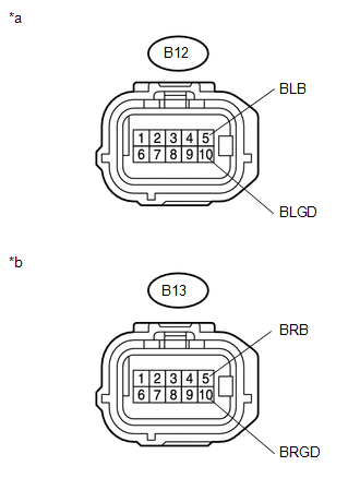
*a |
Front view of wire harness connector (to Blind Spot Monitor Sensor LH) |
|
*b |
Front view of wire harness connector (to Blind Spot Monitor Sensor RH) |
| OK | .gif) |
PROCEED TO NEXT SUSPECTED AREA SHOWN IN PROBLEM SYMPTOMS TABLE |
| NG | |
REPAIR OR REPLACE HARNESS OR CONNECTOR |
 Main Switch Circuit
DESCRIPTION
When the blind spot monitor main switch assembly (warning canceling switch assembly)
is turned on, a signal is sent to the blind spot monitor sensor LH. The blind spot
monitor system ...
 Clearance Sonar Main Switch
Components
COMPONENTS
ILLUSTRATION
Removal
REMOVAL
PROCEDURE
1. REMOVE INSTRUMENT PANEL LOWER CENTER FINISH PANEL
(See page )
2. REMOVE BACK SONAR OR CLEARANCE SONAR SWITCH ASSEMBLY
...
Other materials:
Operation History List
OPERATION HISTORY LIST
NOTICE:
The cause of a malfunction is stored in the RAM or EEPROM in the certification
ECU (smart key ECU assembly). As the cause of a malfunction stored in the
RAM will be cleared when the cable is disconnected from the negative (-)
battery terminal, do ...
Speed Signal Circuit
DESCRIPTION
The combination meter assembly receives the vehicle speed signal from this circuit.
The wheel speed sensors produce an output that varies according to the vehicle speed.
The wheel speed sensor output is received by the skid control ECU, which uses this
information to create the ve ...
Illumination Circuit
DESCRIPTION
Power is supplied to the radio and display receiver assembly and steering pad
switch assembly illumination when the light control switch is in the TAIL or HEAD
position.
WIRING DIAGRAM
CAUTION / NOTICE / HINT
NOTICE:
The vehicle is equipped with a Supplemental Restrain ...
