Toyota Tacoma (2015-2018) Service Manual: Clearance Sonar Main Switch
Components
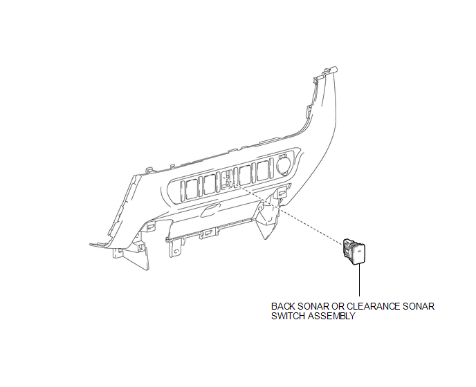
COMPONENTS
ILLUSTRATION
Removal
REMOVAL
PROCEDURE
1. REMOVE INSTRUMENT PANEL LOWER CENTER FINISH PANEL
(See page .gif) )
)
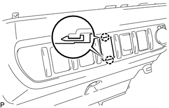
2. REMOVE BACK SONAR OR CLEARANCE SONAR SWITCH ASSEMBLY
|
(a) Disengage the 2 claws to remove the back sonar or clearance sonar switch assembly. |
|
Inspection
INSPECTION
PROCEDURE
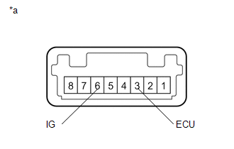
1. INSPECT BACK SONAR OR CLEARANCE SONAR SWITCH ASSEMBLY
(a) Check the resistance.
|
(1) Measure the resistance according to the value(s) in the table below. Text in Illustration
Standard Resistance:
If the result is not as specified, replace the back sonar or clearance sonar switch assembly. |
|
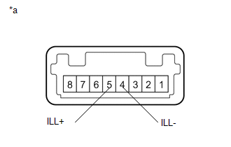
(b) Check the illumination operation.
|
(1) Apply battery voltage to the back sonar or clearance sonar switch assembly and check that the switch illuminates. Text in Illustration
If the result is not as specified, replace the back sonar or clearance sonar switch assembly. |
|
Installation
INSTALLATION
PROCEDURE
1. INSTALL BACK SONAR OR CLEARANCE SONAR SWITCH ASSEMBLY
(a) Engage the 2 claws to install the back sonar or clearance sonar switch assembly.
2. INSTALL INSTRUMENT PANEL LOWER CENTER FINISH PANEL
(See page .gif) )
)
 Power Source Circuit
DESCRIPTION
This circuit provides power to operate the blind spot monitor sensor.
WIRING DIAGRAM
CAUTION / NOTICE / HINT
NOTICE:
Inspect the fuses for circuits related to this system before per ...
 Clearance Warning Buzzer
Components
COMPONENTS
ILLUSTRATION
Installation
INSTALLATION
PROCEDURE
1. INSTALL NO. 1 CLEARANCE WARNING BUZZER
(a) Connect the connector.
(b) Engage the clamp to install the No. 1 clea ...
Other materials:
Front Airbag Sensor LH Circuit Malfunction (B1615/14)
DESCRIPTION
The front airbag sensor LH consists of parts such as the diagnostic circuit and
the frontal detection sensor.
When the airbag sensor assembly receives signals from the frontal deceleration
sensor, it determines whether or not the SRS should be activated.
DTC B1615/14 is set when a ...
Headlight switch
The headlights can be operated manually.
Turning the end of the lever turns on the lights as follows:
Type A
The daytime running lights turn
on.
The side marker, parking, tail,
license plate, daytime running lights and instrument panel lights turn on.
The headlights and all lights lis ...
Air Conditioning Amplifier
Components
COMPONENTS
ILLUSTRATION
Installation
INSTALLATION
PROCEDURE
1. INSTALL AIR CONDITIONING AMPLIFIER ASSEMBLY
(a) Install the air conditioner amplifier assembly with the 2 bolts.
Torque:
7.0 N·m {71 kgf·cm, 62 in·lbf}
(b) Connect the 2 connectors.
2. INSTALL INSTRUMENT L ...
