Toyota Tacoma (2015-2018) Service Manual: Main Switch Circuit
DESCRIPTION
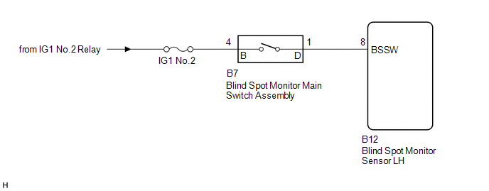
When the blind spot monitor main switch assembly (warning canceling switch assembly) is turned on, a signal is sent to the blind spot monitor sensor LH. The blind spot monitor system operates according to this signal.
WIRING DIAGRAM
CAUTION / NOTICE / HINT
NOTICE:
Inspect the fuse for circuits related to this system before performing the following inspection procedure.
PROCEDURE
|
1. |
READ VALUE USING TECHSTREAM (MAIN SW) |
(a) Connect the Techstream to the DLC3.
(b) Turn the ignition switch to ON.
(c) Turn the Techstream on.
(d) Enter the following menus: Body Electrical / Blind Spot Monitor Master / Data List.
(e) According to the display on the Techstream, read the Data List.
Blind Spot Monitor Master|
Techstream Display |
Measurement Item/Range |
Normal Condition |
Diagnostic Note |
|---|---|---|---|
|
Main SW |
Blind spot monitor main switch assembly / OFF or ON |
ON: Blind spot monitor main switch assembly on OFF: Blind spot monitor main switch assembly off |
- |
|
Result |
Proceed to |
|---|---|
|
The display changes as shown above when the blind spot monitor main switch assembly is operated. |
A |
|
The display does not change as shown above when the blind spot monitor main switch assembly is operated. |
B |
| A | .gif) |
PROCEED TO NEXT SUSPECTED AREA SHOWN IN PROBLEM SYMPTOMS TABLE |
|
.gif)
|
2. |
INSPECT BLIND SPOT MONITOR MAIN SWITCH ASSEMBLY |
(a) Remove the blind spot monitor main switch assembly (See page
.gif) ).
).
(b) Inspect the blind spot monitor main switch assembly (See page
).
| NG | |
REPLACE BLIND SPOT MONITOR MAIN SWITCH ASSEMBLY |
|
|
3. |
CHECK HARNESS AND CONNECTOR (BLIND SPOT MONITOR MAIN SWITCH ASSEMBLY - BATTERY) |
|
(a) Disconnect the blind spot monitor main switch assembly connector. |
|
(b) Measure the voltage according to the value(s) in the table below.
Standard Voltage:
|
Tester Connection |
Switch Condition |
Specified Condition |
|---|---|---|
|
B7-4 (B) - Body ground |
Ignition switch ON |
11 to 14 V |
|
B7-4 (B) - Body ground |
Ignition switch off |
Below 1 V |
|
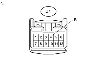
*a |
Front view of wire harness connector (to Blind Spot Monitor Main Switch Assembly) |
| NG | |
REPAIR OR REPLACE HARNESS OR CONNECTOR |
|
|
4. |
CHECK HARNESS AND CONNECTOR (BLIND SPOT MONITOR MAIN SWITCH ASSEMBLY - BLIND SPOT MONITOR SENSOR LH) |
(a) Disconnect the B12 blind spot monitor sensor LH connector.
(b) Disconnect the B7 blind spot monitor main switch assembly connector.
(c) Measure the resistance according to the value(s) in the table below.
Standard Resistance:
|
Tester Connection |
Condition |
Specified Condition |
|---|---|---|
|
B12-8 (BSSW) - B7-1 (D) |
Always |
Below 1 Ω |
|
B12-8 (BSSW) - Body ground |
Always |
10 kΩ or higher |
| OK | |
REPLACE BLIND SPOT MONITOR SENSOR LH |
| NG | |
REPAIR OR REPLACE HARNESS OR CONNECTOR |
 Master Module Horizontal Axis Misalignment (C1AC1)
DESCRIPTION
This DTC is stored when the angle of the blind spot monitor sensor LH deviates
more than the allowable range from the horizontal axis.
HINT:
If drum tester such as a speedometer teste ...
 Power Source Circuit
DESCRIPTION
This circuit provides power to operate the blind spot monitor sensor.
WIRING DIAGRAM
CAUTION / NOTICE / HINT
NOTICE:
Inspect the fuses for circuits related to this system before per ...
Other materials:
Operation Check
OPERATION CHECK
1. CHECK NAVIGATION SYSTEM NORMAL CONDITION
(a) If the symptom is applicable to any of the following, it is intended behavior,
and not a malfunction.
Symptom
Answer
A longer route than expected is chosen.
Depending on the road co ...
Transponder Chip Malfunction (B2793,B2794,B2797,B2798)
DESCRIPTION
DTC B2793 is stored when a malfunction is found in the key during key
code registration or a key code is not registered normally. Replace the
key if key code registration cannot be performed normally and this DTC is
output.
DTC B2794 is stored when a key with an i ...
Transmission Range Sensor "A" Circuit Open (P070513,P070562)
DESCRIPTION
The park/neutral position switch detects the shift lever position and sends signals
to the ECM.
DTC No.
DTC Detection Condition
Trouble Area
SAE
P070513
All of the following signals are OFF simultaneously for 60 ...
