Toyota Tacoma (2015-2018) Service Manual: Pattern Select Switch Power Mode Circuit
DESCRIPTION
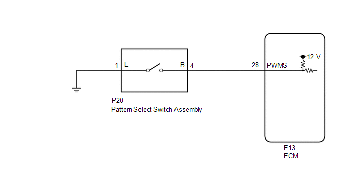
The ECM memory contains the programs for the normal and PWR shift patterns.
By following the programs corresponding to the signals from the pattern select switch assembly, park/neutral position switch and other various sensors, the ECM switches the shift solenoid valves on and off, and controls the transmission gear ratio.
WIRING DIAGRAM
PROCEDURE
|
1. |
INSPECT PATTERN SELECT SWITCH ASSEMBLY |
|
(a) Remove the pattern select switch assembly (See page
|
|
.gif) ).
).
(b) Measure the resistance according to the value(s) in the table below.
Standard Resistance:
|
Tester Connection |
Switch Condition |
Specified Condition |
|---|---|---|
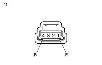
|
1 (E) - 4 (B) |
Pattern select switch assembly pushed |
Below 1 Ω |
|
1 (E) - 4 (B) |
Pattern select switch assembly not pushed |
10 kΩ or higher |
|
*1 |
Pattern Select Switch Assembly |
| NG | .gif) |
REPLACE PATTERN SELECT SWITCH ASSEMBLY |
|
.gif)
|
2. |
CHECK HARNESS AND CONNECTOR (PATTERN SELECT SWITCH ASSEMBLY - BODY GROUND) |
|
(a) Disconnect the pattern select switch assembly connector. |
|
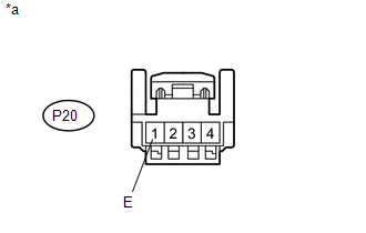
(b) Measure the resistance according to the value(s) in the table below.
Standard Resistance:
|
Tester Connection |
Condition |
Specified Condition |
|---|---|---|
|
P20-1 (E) - Body ground |
Always |
Below 1 Ω |
|
*a |
Front view of wire harness connector (to Pattern Select Switch Assembly) |
| NG | |
REPAIR OR REPLACE HARNESS OR CONNECTOR |
|
|
3. |
CHECK HARNESS AND CONNECTOR (PATTERN SELECT SWITCH ASSEMBLY - ECM) |
|
(a) Disconnect the ECM connector. |
|
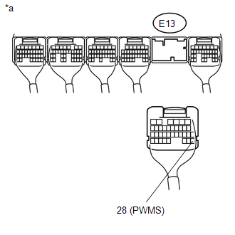
(b) Measure the resistance according to the value(s) in the table below.
Standard Resistance:
|
Tester Connection |
Switch Condition |
Specified Condition |
|---|---|---|
|
E13-28 (PWMS) - Body ground |
Pattern select switch assembly pushed |
Below 1 Ω |
|
E13-28 (PWMS) - Body ground |
Pattern select switch assembly not pushed |
10 kΩ or higher |
|
*a |
Rear view of wire harness connector (to ECM) |
| OK | |
PROCEED TO NEXT SUSPECTED AREA SHOWN IN PROBLEM SYMPTOMS TABLE |
| NG | |
REPAIR OR REPLACE HARNESS OR CONNECTOR |
 Torque Converter Clutch Pressure Control Solenoid Control Circuit Open (P275613)
DESCRIPTION
Refer to the system description for DTC P27567F (See page
).
DTC No.
DTC Detection Condition
Trouble Area
SAE
P275613
...

Other materials:
Precaution
PRECAUTION
1. EXPRESSIONS OF IGNITION SWITCH
HINT:
The type of ignition switch used on this model differs according to the specifications
of the vehicle. The expressions listed in the table below are used in this section.
Expression
Ignition Switch
(Position)
...
Removal
REMOVAL
PROCEDURE
1. PRECAUTION
NOTICE:
After turning the ignition switch off, waiting time may be required before disconnecting
the cable from the negative (-) battery terminal. Therefore, make sure to read the
disconnecting the cable from the negative (-) battery terminal notices before pr ...
Does not Play even after Bluetooth Audio Mode is Selected
CAUTION / NOTICE / HINT
HINT:
Even if the portable player can play audio content, it may not be able to play
via the in-vehicle device. This does not necessarily indicate a malfunction of the
in-vehicle device.
PROCEDURE
1.
CHECK OPERATION
(a) Check if the po ...
