Toyota Tacoma (2015-2018) Service Manual: Torque Converter Clutch Pressure Control Solenoid Control Circuit Open (P275613)
DESCRIPTION
Refer to the system description for DTC P27567F (See page
.gif) ).
).
|
DTC No. |
DTC Detection Condition |
Trouble Area |
SAE |
|---|---|---|---|
|
P275613 |
Open or short is detected in shift solenoid valve SLU circuit for 1 second or more while driving (1 trip detection logic). |
|
P2759 |
MONITOR DESCRIPTION
When an open or short in a shift solenoid valve SLU circuit is detected, the ECM determines there is a malfunction. The ECM will illuminate the MIL and store this DTC.
MONITOR STRATEGY
|
Related DTCs |
P2759: Shift solenoid valve SLU/Range check |
|
Required sensors/Components |
Shift solenoid valve SLU |
|
Frequency of operation |
Continuous |
|
Duration |
1 sec. |
|
MIL operation |
Immediately |
|
Sequence of operation |
None |
TYPICAL ENABLING CONDITIONS
All:|
The monitor will run whenever the following DTCs are not stored |
None |
|
Solenoid current cut status |
Not cut |
|
Ignition switch |
ON |
|
Starter |
OFF |
|
Battery voltage |
12 V or higher |
|
Battery voltage |
10 V or higher, and below 12 V |
|
Target current |
Below 0.75 A |
|
Battery voltage |
8 V or higher |
|
Target current |
0.25 A or higher |
TYPICAL MALFUNCTION THRESHOLDS
One of the following conditions is met: Condition (A), (B) or (C)
Condition (A) and (B):|
Output duty cycle |
More than 100% |
|
Output duty cycle |
Less than 0% |
COMPONENT OPERATING RANGE
|
Output duty cycle |
More than 3%, and less than 100% |
CONFIRMATION DRIVING PATTERN
CAUTION:
When performing the confirmation driving pattern, obey all speed limits and traffic laws.
HINT:
- After repairs have been completed, clear the DTCs and then check that the vehicle has returned to normal by performing the following All Readiness check procedure.
- When clearing the permanent DTCs, refer to the Clear Permanent DTC procedure
(See page ).
- Connect the Techstream to the DLC3.
- Turn the ignition switch to ON and turn the Techstream on.
- Clear the DTCs (even if no DTCs are stored, perform the clear DTC procedure).
- Turn the ignition switch off and wait for 2 minutes or more.
- Turn the ignition switch to ON and turn the Techstream on.
- Start the engine.
- Perform the Lock-up Function inspection in Road Test (See page
). [*1]
HINT:
[*1] : Normal judgment procedure.
The normal judgment procedure is used to complete DTC judgment and also used when clearing permanent DTCs.
- Enter the following menus: Powertrain / Transmission / Utility / All Readiness.
- Input the DTC: P275613.
- Check the DTC judgment result.
Techstream Display
Description
NORMAL
- DTC judgment completed
- System normal
ABNORMAL
- DTC judgment completed
- System abnormal
INCOMPLETE
- DTC judgment not completed
- Perform driving pattern after confirming DTC enabling conditions
N/A
- Unable to perform DTC judgment
- Number of DTCs which do not fulfill DTC preconditions has reached ECU memory limit
HINT:
- If the judgment result shows NORMAL, the system is normal.
- If the judgment result shows ABNORMAL, the system has a malfunction.
- If the judgment result shows INCOMPLETE or N/A, perform the normal judgment procedure again.
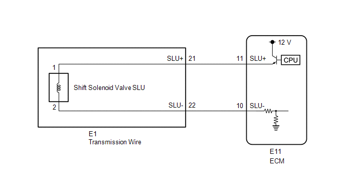
WIRING DIAGRAM
CAUTION / NOTICE / HINT
NOTICE:
- Perform the universal trip to clear permanent DTCs (See page
).
- Perform registration and/or initialization when parts related to the
automatic transmission are replaced (See page
).
PROCEDURE
|
1. |
INSPECT TRANSMISSION WIRE (SHIFT SOLENOID VALVE SLU) |
|
(a) Disconnect the E1 transmission wire connector. |
|
(b) Measure the resistance according to the value(s) in the table below.
Standard Resistance:
|
Tester Connection |
Condition |
Specified Condition |
|---|---|---|
|
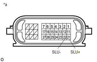
21 (SLU+) - 22 (SLU-) |
20°C (68°F) |
5.0 to 5.6 Ω |
|
21 (SLU+) - Body ground |
Always |
10 kΩ or higher |
|
22 (SLU-) - Body ground |
Always |
10 kΩ or higher |
|
*a |
Component without harness connected (Transmission Wire) |
| NG | .gif) |
GO TO STEP 3 |
|
.gif)
|
2. |
CHECK HARNESS AND CONNECTOR (TRANSMISSION WIRE - ECM) |
|
(a) Disconnect the ECM connector. |
|
(b) Measure the resistance according to the value(s) in the table below.
Standard Resistance:
|
Tester Connection |
Condition |
Specified Condition |
|---|---|---|
|
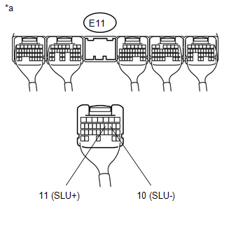
E11-11 (SLU+) - E11-10 (SLU-) |
20°C (68°F) |
5.0 to 5.6 Ω |
|
E11-11 (SLU+) - Body ground |
Always |
10 kΩ or higher |
|
E11-10 (SLU-) - Body ground |
Always |
10 kΩ or higher |
|
*a |
Rear view of wire harness connector (to ECM) |
| OK | |
REPLACE ECM |
| NG | |
REPAIR OR REPLACE HARNESS OR CONNECTOR |
|
3. |
INSPECT SHIFT SOLENOID VALVE SLU |
|
(a) Remove shift solenoid valve SLU (See page
|
|
.png)
(b) Measure the resistance according to the value(s) in the table below.
Standard Resistance:
|
Tester Connection |
Condition |
Specified Condition |
|---|---|---|
|
1 - 2 |
20°C (68°F) |
5.0 to 5.6 Ω |
(c) Apply 12 V battery voltage to the shift solenoid valve and check that the valve moves and makes an operating noise.
OK:
|
Measurement Condition |
Specified Condition |
|---|---|
|
Valve moves and makes an operating noise |
|
*1 |
Shift Solenoid Valve SLU |
| OK | |
REPLACE TRANSMISSION WIRE |
| NG | |
REPLACE SHIFT SOLENOID VALVE SLU |
 Transmission Fluid Temperature Sensor "A" Circuit Range/Performance (P071000)
DESCRIPTION
The No. 1 ATF temperature sensor converts the fluid temperature into a resistance
value for use by the ECM.
The ECM applies a voltage to the temperature sensor through terminal THO1 of ...
 Pattern Select Switch Power Mode Circuit
DESCRIPTION
The ECM memory contains the programs for the normal and PWR shift patterns.
By following the programs corresponding to the signals from the pattern select
switch assembly, park/neutral ...
Other materials:
Driver Side Seat Heater does not Operate
DESCRIPTION
When the seat heater switch on the air conditioning control assembly is operated,
the air conditioning amplifier assembly receives the signal. The air conditioning
amplifier assembly receives the signal and operates the front seat heater.
WIRING DIAGRAM
CAUTION / NOTICE / HINT
...
TC and CG Terminal Circuit
DESCRIPTION
The DLC3 circuit enables reading of Diagnostic Trouble Codes (DTCs) with no Techstream
by connecting terminals TC and CG of the DLC3 connector.
Stored DTCs are displayed in blinking patterns of the CRUISE MAIN indicator light
located on the combination meter.
WIRING DIAGRAM
HIN ...
Brake System (P157800)
DESCRIPTION
This DTC is output when the VSC system has a problem. Check the VSC system when
this DTC is output.
DTC No.
DTC Detection Condition
Trouble Area
MIL
Note
P157800
Diagnosis Condition:
Cr ...
