Toyota Tacoma (2015-2018) Service Manual: Installation
INSTALLATION
CAUTION / NOTICE / HINT
NOTICE:
If the millimeter wave radar sensor assembly has been struck or dropped, replace the millimeter wave radar sensor assembly with a new one.
PROCEDURE
1. INSTALL MILLIMETER WAVE RADAR SENSOR ASSEMBLY
|
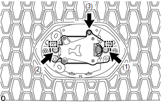
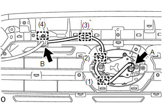
(a) for Type A: (1) Engage the 2 guides. (2) Temporarily install the millimeter wave radar sensor assembly with the 2 bolts and screw. (3) Tighten the 2 bolts and screw in the order shown in the illustration. Torque: Bolt : 2.5 N·m {25 kgf·cm, 22 in·lbf} |
|
|
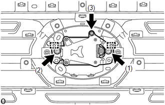
(b) for Type B: (1) Engage the 2 guides. (2) Temporarily install the millimeter wave radar sensor assembly with the 2 bolts and screw. (3) Tighten the 2 bolts and screw in the order shown in the illustration. Torque: Bolt : 2.5 N·m {25 kgf·cm, 22 in·lbf} |
|
|
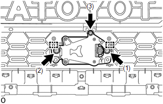
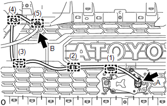
(c) for Type C: (1) Engage the 2 guides. (2) Temporarily install the millimeter wave radar sensor assembly with the 2 bolts and screw. (3) Tighten the 2 bolts and screw in the order shown in the illustration. Torque: Bolt : 2.5 N·m {25 kgf·cm, 22 in·lbf} |
|
2. INSTALL MILLIMETER WAVE RADAR WIRE
|
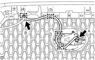
(a) for Type A: (1) Connect the connector A. (2) Engage the 4 clamps to install the millimeter wave radar wire in the order shown in the illustration. (3) Connect the connector B. |
|
|
(b) for Type B: (1) Connect the connector A. (2) Engage the 4 clamps to install the millimeter wave radar wire in the order shown in the illustration. (3) Connect the connector B. |
|
|
(c) for Type C: (1) Connect the connector A. (2) Engage the 5 clamps to install the millimeter wave radar wire in the order shown in the illustration. (3) Connect the connector B. |
|
3. ADJUST MILLIMETER WAVE RADAR SENSOR ASSEMBLY
(a) When the millimeter wave radar sensor assembly is replaced, adjust the millimeter wave radar sensor assembly.
Click here .gif)
 Removal
REMOVAL
PROCEDURE
1. REMOVE MILLIMETER WAVE RADAR WIRE
(a) for Type A:
(1) Disconnect the 2 connectors.
(2) Using a clip remover, disengage the 4 clamps to remove the millimeter
...
 Differential
...
Other materials:
Operation Check
OPERATION CHECK
1. CHECK PANEL & STEERING SWITCH
HINT:
The radio and display receiver assembly panel switches and steering
switches are checked in the following procedure.
Illustrations may differ from the actual vehicle screen depending on
the device settings and options. ...
Data List / Active Test
DATA LIST / ACTIVE TEST
1. DATA LIST
HINT:
Using the Techstream to read the Data List allows the values or states of switches,
sensors, actuators and other items to be read without removing any parts. This non-intrusive
inspection can be very useful because intermittent conditions or signals ...
Dtc Check / Clear
DTC CHECK / CLEAR
1. DTC CHECK/CLEAR (When Using Techstream)
(a) Check the DTC.
(1) Turn the ignition switch off.
(2) Connect the Techstream to the DLC3.
(3) Turn the ignition switch to ON.
(4) Turn the Techstream on.
(5) Read the DTCs following the prompts on the Techstream screen. Enter the ...
