Toyota Tacoma (2015-2018) Service Manual: Parts Location
PARTS LOCATION
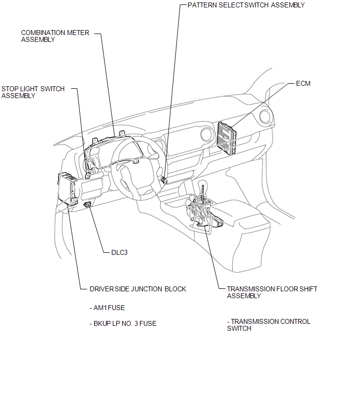
ILLUSTRATION
.png)
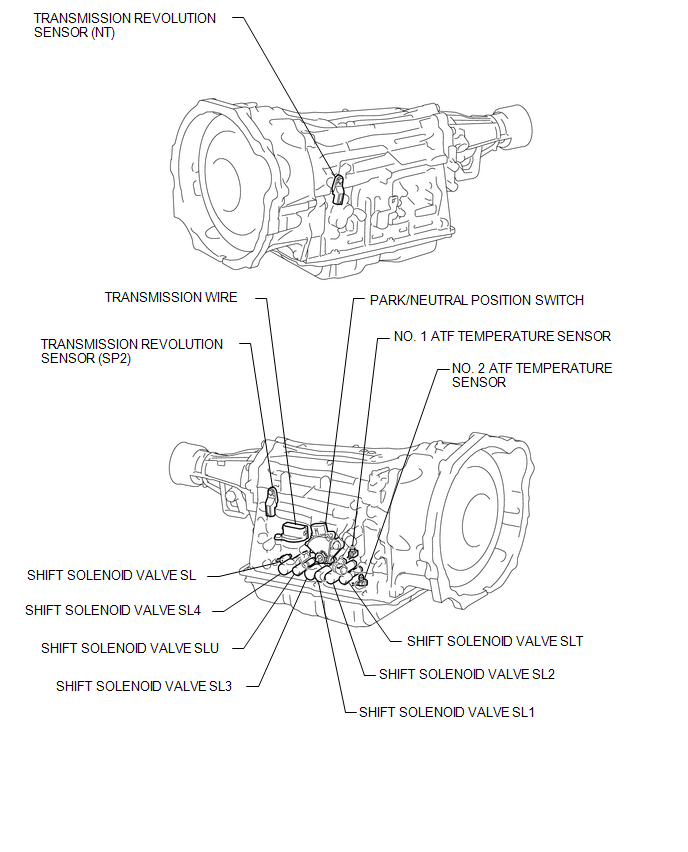
ILLUSTRATION
ILLUSTRATION
 Definition Of Terms
DEFINITION OF TERMS
Term
Definition
Monitor description
Description of what the ECM monitors and how it detects malfunctions
(monitoring purpose ...
 How To Proceed With Troubleshooting
CAUTION / NOTICE / HINT
HINT:
The ECM of this system is connected to the CAN communication system.
Therefore, before starting troubleshooting, make sure to check that there
is no tro ...
Other materials:
Lost Communication with ECM / PCM "A" (U0100,U0126,U0129,U0142)
DESCRIPTION
These DTCs are stored if there is a malfunction in the CAN communication system
connected to the blind spot monitor sensor.
HINT:
If CAN communication system DTCs are stored, they may also be stored for other
systems.
DTC Code
DTC Detection Condition
...
Problem Symptoms Table
PROBLEM SYMPTOMS TABLE
HINT:
Use the table below to help determine the cause of problem symptoms.
If multiple suspected areas are listed, the potential causes of the symptoms
are listed in order of probability in the "Suspected Area" column of the
table. Check each sy ...
If the shift lever cannot be shifted from P (vehicles with an automatic transmission)
If the shift lever cannot be shifted with your foot on the brake, there may
be a problem with the shift lock system (a system to prevent accidental operation
of the shift lever). Have the vehicle inspected by your Toyota dealer immediately.
The following steps may be used as an emergency measur ...
