Toyota Tacoma (2015-2018) Service Manual: 4wd Control Ecu
Components
COMPONENTS
ILLUSTRATION
Installation
INSTALLATION
PROCEDURE
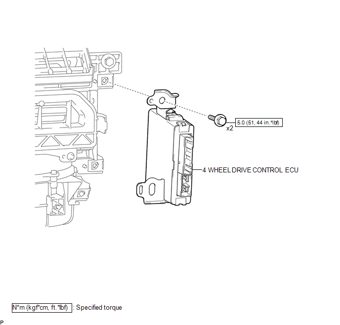
1. INSTALL 4 WHEEL DRIVE CONTROL ECU
(a) Engage the 2 guides to install the 4 wheel drive control ECU.
(b) Install the 2 bolts.
Torque:
5.0 N·m {51 kgf·cm, 44 in·lbf}
(c) Connect the 2 connectors.
2. INSTALL ECM
(See page .gif) )
)
Removal
REMOVAL
PROCEDURE
1. REMOVE ECM
(See page .gif) )
)
2. REMOVE 4 WHEEL DRIVE CONTROL ECU
|
(a) Disconnect the 2 connectors. |
|
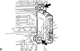
(b) Remove the 2 bolts.
(c) Disengage the 2 guides to remove the 4 wheel drive control ECU.
 Vf2cm Transfer
...

Other materials:
Inspection
INSPECTION
PROCEDURE
1. INSPECT FUEL PUMP ASSEMBLY
(a) Measure the resistance according to the value(s) in the table below.
Standard Resistance:
Tester Connection
Condition
Specified Condition
1 - 2
20°C (68°F)
0.45 to 0 ...
Reassembly
REASSEMBLY
PROCEDURE
1. INSTALL RADIATOR GRILLE MOULDING
(a) Engage the 8 claws to install the radiator grille moulding.
(b) Install the 8 screws.
2. INSTALL NO. 1 RADIATOR GRILLE GARNISH
(a) for Type A and Type B:
(1) Engag ...
Inner Rear View Mirror
Components
COMPONENTS
ILLUSTRATION
ILLUSTRATION
Calibration
CALIBRATION
1. SELECT COMPASS DISPLAY MODE
(a) The compass switch allows you to select the Display or Non-display mode of
the compass.
*1
Compass Switch / EC Control Switch
2. PERFORM CALI ...
