Toyota Tacoma (2015-2018) Service Manual: Installation
INSTALLATION
PROCEDURE
1. INSPECT FRONT PROPELLER SHAFT ASSEMBLY (with Grease Fitting)
HINT:
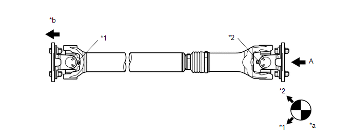
When replacing the spider bearing, make sure that the grease fitting assembly hole is facing in the direction shown in the illustration.
 Text in Illustration
|
*1 |
No. 1 Grease Fitting |
*2 |
No. 2 Grease Fitting |
|
*a |
View A |
*b |
Front Side |
2. INSTALL FRONT PROPELLER SHAFT ASSEMBLY
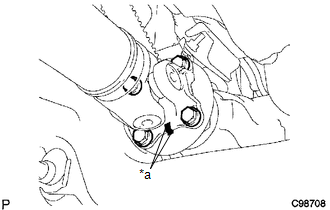
(a) Align the matchmarks on the propeller shaft flange and differential flange.
Text in Illustration|
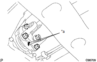
*a |
Matchmark |
(b) Install the propeller shaft with the 4 bolts, 4 nuts and 4 washers.
Torque:
88 N·m {899 kgf·cm, 65 ft·lbf}
|
(c) Align the matchmarks on the propeller shaft flange and transfer flange. Text in Illustration
|
|
(d) Install the propeller shaft with the 4 nuts and 4 washers.
Torque:
88 N·m {899 kgf·cm, 65 ft·lbf}
3. INSTALL PROPELLER SHAFT HEAT INSULATOR BRACKET SUB-ASSEMBLY
.png)
(a) Install the propeller shaft heat insulator bracket with the 2 bolts.
Torque:
16 N·m {160 kgf·cm, 12 ft·lbf}
4. INSTALL FRONT NO. 2 EXHAUST PIPE ASSEMBLY (for 2GR-FKS)
.gif)
 Reassembly
REASSEMBLY
PROCEDURE
1. INSTALL FRONT PROPELLER SHAFT UNIVERSAL JOINT SPIDER BEARING
(a) Apply MP grease to a new spider and spider bearing.
(b) Fit the spider into the flange yoke.
...

Other materials:
Radio Antenna Cord
Components
COMPONENTS
ILLUSTRATION
Removal
REMOVAL
PROCEDURE
1. REMOVE INSTRUMENT PANEL SUB-ASSEMBLY
(See page )
2. REMOVE ANTENNA CORD SUB-ASSEMBLY
(a) Disengage the 4 clamps to remove the antenna cord sub-assembly.
Installation
INSTALLATION
PROCEDURE
1. INSTALL ANTENNA COR ...
On-vehicle Inspection
ON-VEHICLE INSPECTION
PROCEDURE
1. INSPECT INSTRUMENT PANEL PASSENGER AIRBAG ASSEMBLY WITHOUT DOOR (for Vehicle
not Involved in Collision)
(a) Perform a diagnostic system check (See page
).
(b) With the instrument panel passenger airbag ...
System Diagram
SYSTEM DIAGRAM
Communication Table
Sender
Receiver
Signal
Line
*1: for Vacuum Brake Booster
*2: for Hydraulic Brake Booster
Millimeter Wave Radar Sensor Assembly
Forward Recognition Camera
...
