Toyota Tacoma (2015-2018) Service Manual: Parts Location
PARTS LOCATION
ILLUSTRATION
|
*A |
for Automatic Transmission |
- |
- |
|
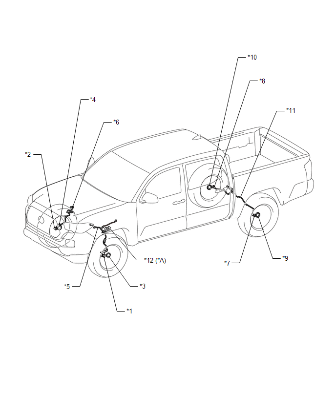
*1 |
FRONT SPEED SENSOR LH |
*2 |
FRONT SPEED SENSOR RH |
|
*3 |
FRONT AXLE WITH ABS ROTOR BEARING ASSEMBLY LH - FRONT SPEED SENSOR ROTOR LH |
*4 |
FRONT AXLE WITH ABS ROTOR BEARING ASSEMBLY RH - FRONT SPEED SENSOR ROTOR RH |
|
*5 |
FRONT SKID CONTROL SENSOR WIRE LH |
*6 |
FRONT SKID CONTROL SENSOR WIRE RH |
|
*7 |
REAR SPEED SENSOR LH |
*8 |
REAR SPEED SENSOR RH |
|
*9 |
REAR AXLE HUB AND BEARING ASSEMBLY LH - REAR SPEED SENSOR ROTOR LH |
*10 |
REAR AXLE HUB AND BEARING ASSEMBLY RH - REAR SPEED SENSOR ROTOR RH |
|
*11 |
REAR SKID CONTROL SENSOR WIRE |
*12 |
PARK/NEUTRAL POSITION SWITCH |
ILLUSTRATION
|
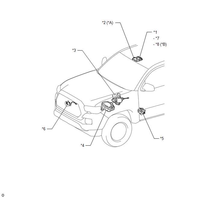
*A |
for Automatic Transmission |
*B |
for Manual Transmission |
|
*1 |
ROOF CONSOLE BOX ASSEMBLY |
*2 |
DRIVE MONITOR SWITCH - CRAWL CONTROL SWITCH - MULTI-TERRAIN SELECT SWITCH |
|
*3 |
HYDRAULIC BRAKE BOOSTER - SKID CONTROL ECU (MASTER CYLINDER SOLENOID) - BRAKE FLUID LEVEL WARNING SWITCH (BRAKE MASTER CYLINDER RESERVOIR SUB-ASSEMBLY) - MASTER CYLINDER PRESSURE SENSOR |
*4 |
ENGINE ROOM RELAY BLOCK AND JUNCTION BLOCK - STOP RELAY - STOP FUSE - ABS NO. 1 FUSE - ABS NO. 2 FUSE - ECU-B NO. 2 FUSE |
|
*5 |
TRANSFER SHIFT ACTUATOR ASSEMBLY - 4WD DETECTION SWITCH - L4 DETECTION SWITCH |
*6 |
MILLIMETER WAVE RADAR SENSOR ASSEMBLY |
|
*7 |
VSC OFF SWITCH |
*8 |
A-TRAC SWITCH |
ILLUSTRATION
|
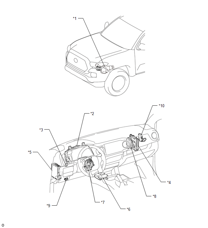
*1 |
DIFFERENTIAL VACUUM ACTUATOR ASSEMBLY - A.D.D. POSITION SWITCH |
*2 |
COMBINATION METER ASSEMBLY |
|
*3 |
STOP LIGHT SWITCH ASSEMBLY |
*4 |
ECM |
|
*5 |
DRIVER SIDE JUNCTION BLOCK - ECU-IG NO. 3 FUSE - IG2 FUSE - IG1 NO. 1 FUSE - A/BAG FUSE |
*6 |
AIRBAG SENSOR ASSEMBLY - YAW RATE AND ACCELERATION SENSOR |
|
*7 |
SPIRAL CABLE WITH SENSOR SUB-ASSEMBLY - STEERING ANGLE SENSOR |
*8 |
4 WHEEL DRIVE CONTROL ECU |
|
*9 |
DLC3 |
*10 |
NETWORK GATEWAY ECU |

 Precaution
PRECAUTION
1. IGNITION SWITCH EXPRESSION
(a) The type of ignition switch used on this model differs depending on the specifications
of the vehicle. The expressions listed in the table below are us ...
Other materials:
Problem Symptoms Table
PROBLEM SYMPTOMS TABLE
HINT:
Use the table below to help determine the cause of problem symptoms.
If multiple suspected areas are listed, the potential causes of the symptoms
are listed in order of probability in the "Suspected Area" column of the
table. Check each sy ...
Inspection
INSPECTION
PROCEDURE
1. INSPECT TRANSMISSION FLOOR SHIFT ASSEMBLY (w/o Smart Key System)
HINT:
If the results of the following inspections are as specified but a malfunction
has occurred, replace the transmission floor shift assembly.
(a) Inspect the wire harness.
(1) Disconnect the shift lo ...
Operation Check
OPERATION CHECK
1. CHECK WINDOW LOCK SWITCH
HINT:
Before performing the window lock switch operation check, make sure that the
window lock switch is off (the switch is not pushed in).
(a) Check that the front passenger and rear windows cannot be operated from each
power window regulator swit ...
