Toyota Tacoma (2015-2018) Service Manual: Terminals Of Ecu
TERMINALS OF ECU
 Text in Illustration
|
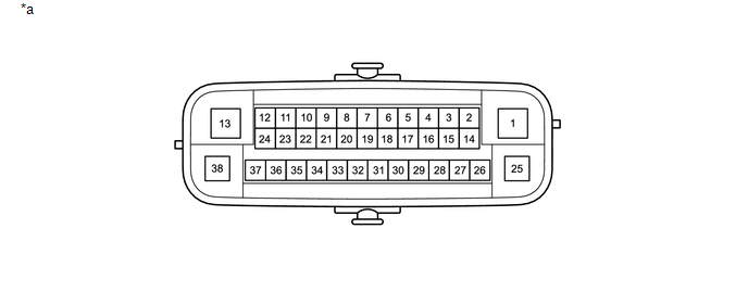
*a |
Component without harness connected (Skid Control ECU [Brake Actuator Assembly]) |
- |
- |
|
Terminal No. (Symbol) |
Terminal Description |
|---|---|
|
1 (GND2) |
Pump motor ground |
|
2 |
- (Not used) |
|
3 (EXI)*1 |
4WD detection switch (Transfer shift actuator assembly) input |
|
A.D.D. position switch (Differential motor actuator assembly) signal input |
|
|
4 |
- (Not used) |
|
5 (EXI4)*1 |
L4 detection switch (Transfer shift actuator assembly) input |
|
6 |
- (Not used) |
|
7 (STP2)*2 |
Stop light switch assembly input |
|
8 |
- (Not used) |
|
9 |
- (Not used) |
|
10 (CANL) |
CAN communication line L |
|
11 (EXI3) |
Back up light sw input |
|
12 (IG1) |
ECU power supply input |
|
13 (BM) |
Motor relay power supply |
|
14 (SP1) |
Speed signal output for speedometer |
|
15 (RR-) |
Rear wheel speed RH (-) signal input |
|
16 (RR+) |
Rear wheel speed RH (+) power supply output |
|
17 (FL-) |
Front wheel speed LH (-) signal input |
|
18 (FL+) |
Front wheel speed LH (+) power supply output |
|
19 |
- (Not used) |
|
20 |
- (Not used) |
|
21 |
- (Not used) |
|
22 (CANH) |
CAN communication line H |
|
23 |
- (Not used) |
|
24 (TS)*3 |
Sensor check input |
|
25 (GND1) |
Skid control ECU (Brake actuator assembly) ground |
|
26 (STPO)*2 |
STOP Relay output |
|
27 (HDCS) |
4WD identification signal input*1 |
|
28 (RL-) |
Rear wheel speed LH (-) signal input |
|
29 (RL+) |
Rear wheel speed LH (+) power supply output |
|
30 (FR-) |
Front wheel speed RH (-) signal input |
|
31 (FR+) |
Front wheel speed RH (+) power supply output |
|
32 |
- (Not used) |
|
33 (CSW) |
VSC OFF switch input |
|
34 |
- (Not used) |
|
35 (STP) |
STOP Relay input |
|
36 |
- (Not used) |
|
37 |
- (Not used) |
|
38 (+BS) |
Solenoid relay power supply |
- *1: for 4WD
- *2: w/ Trailer Towing
- *3: w/o Toyota Safety Sense P
1. TERMINAL INSPECTION
(a) Disconnect the connector and measure the voltage or resistance on the wire harness side.
 Text in Illustration
|
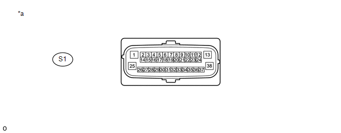
*a |
Front view of wire harness connector (to Skid Control ECU [Brake Actuator Assembly]) |
- |
- |
HINT:
Voltage cannot be measured with the connector connected to the skid control (brake actuator assembly) as the connector is watertight.
|
Terminal No. (Symbol) |
Wiring Color |
Terminal Description |
Condition |
Specified Condition |
|---|---|---|---|---|
|
S1-1 (GND2) - Body ground |
W-B - Body ground |
Pump motor ground |
Always |
Below 1 Ω |
|
S1-3 (EXI) - Body ground*1 |
LG - Body ground |
4WD detection switch (Transfer shift actuator assembly) input |
|
11 to 14 V |
|
A.D.D. position switch (Differential motor actuator assembly) signal input |
|
11 to 14 V |
||
|
S1-5 (EXI4) - Body ground*1 |
GR - Body ground |
L4 detection switch (Transfer shift actuator assembly) input |
|
11 to 14 V |
|
S1-7 (STP2) - Body ground |
L - Body ground |
Stop light switch assembly input |
Stop light switch assembly on → off (Brake pedal depressed → released) |
8 to 14 V → Below 1.5 V |
|
S1-12 (IG1) - Body ground |
G - Body ground |
ECU power supply input |
Ignition switch ON |
11 to 14 V |
|
S1-13 (BM) - Body ground |
B - Body ground |
Motor relay power supply |
Always |
11 to 14 V |
|
S1-14 (SP1) - Body ground |
G - Body ground |
Speed signal output for speedometer |
Ignition switch ON |
11 to 14 V |
|
S1-25 (GND1) - Body ground |
W-B - Body ground |
Skid control ECU (Brake actuator assembly) ground |
Always |
Below 1 Ω |
|
S1-26 (STPO) - Body ground |
B - Body ground |
STOP Relay output |
Ignition switch ON |
11 to 14 V |
|
S1-33 (CSW) - Body ground |
GR - Body ground |
VSC OFF switch input |
VSC OFF switch pressed and held → released |
Below 1 Ω → 10 kΩ or higher |
|
S1-35 (STP) - Body ground |
SB - Body ground |
STOP Relay input |
Stop light switch assembly on → off (Brake pedal depressed → released) |
8 to 14 V → Below 1.5 V |
|
S1-38 (+BS) - Body ground |
R - Body ground |
Solenoid relay power supply |
Always |
11 to 14 V |
- *1: for 4WD
 Diagnosis System
DIAGNOSIS SYSTEM
1. DESCRIPTION
When troubleshooting a vehicle with the diagnosis system, the only difference
from the usual troubleshooting procedure is connecting the Techstream to the vehicle
...
 Dtc Check / Clear
DTC CHECK / CLEAR
1. DTC CHECK/CLEAR (When Using Techstream)
(a) Check the DTC.
(1) Turn the ignition switch off.
(2) Connect the Techstream to the DLC3.
(3) Turn the ignition switch to ON.
(4) ...
Other materials:
Fuel information
Your vehicle must use only unleaded gasoline.
Select octane rating 87 (Research Octane Number 91) or higher. Use of unleaded
gasoline with an octane rating lower than 87 may result in engine knocking. Persistent
knocking can lead to engine damage.
At minimum, the gasoline you use should meet t ...
Removal
REMOVAL
PROCEDURE
1. PRECAUTION
NOTICE:
After turning the ignition switch off, waiting time may be required before disconnecting
the cable from the battery terminal. Therefore, make sure to read the disconnecting
the cable from the battery terminal notice before proceeding with work.
Click ...
On-vehicle Inspection
ON-VEHICLE INSPECTION
PROCEDURE
1. INSPECT FRONT SEAT AIRBAG ASSEMBLY LH (for Vehicle not Involved in Collision)
(a) Perform a diagnostic system check (See page
).
(b) With the front seat airbag assembly LH installed on the vehicle, perfor ...
