Toyota Tacoma (2015-2018) Service Manual: Installation
INSTALLATION
PROCEDURE
1. INSTALL LOWER NO. 2 INSTRUMENT PANEL AIRBAG ASSEMBLY
|
(a) Connect the airbag connector. NOTICE: When handling the airbag connector, take care not to damage the airbag wire harness. |
|
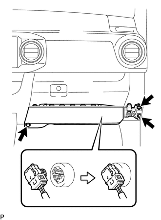
(b) Push in the airbag connector lock to install the airbag connector.
(c) Install the lower No. 2 instrument panel airbag assembly with the 3 bolts.
Torque:
10 N·m {102 kgf·cm, 7 ft·lbf}
2. INSTALL GLOVE COMPARTMENT PLATE
.gif)
3. INSTALL INSTRUMENT SIDE PANEL RH
4. CONNECT CABLE TO NEGATIVE BATTERY TERMINAL
Torque:
5.4 N·m {55 kgf·cm, 48 in·lbf}
NOTICE:
When disconnecting the cable, some systems need to be initialized after the cable is reconnected.
Click here
5. INSPECT SRS WARNING LIGHT
Click here
 Components
COMPONENTS
ILLUSTRATION
...
 On-vehicle Inspection
ON-VEHICLE INSPECTION
PROCEDURE
1. INSPECT LOWER NO. 2 INSTRUMENT PANEL AIRBAG ASSEMBLY (for Vehicle not Involved
in Collision)
(a) Perform a diagnostic system check (See page
).
...
Other materials:
Data List / Active Test
DATA LIST / ACTIVE TEST
1. DATA LIST
HINT:
Using the Techstream to read the Data List allows the values or states of switches,
sensors, actuators and other items to be read without removing any parts. This non-intrusive
inspection can be very useful because intermittent conditions or signals ...
System Diagram
SYSTEM DIAGRAM
Transmitting ECU (Transmitter)
Receiving ECU
Signal
Communication Method
Skid control ECU (Brake actuator assembly)
Steering angle sensor (Spiral cable with sensor sub-assembly)
Steering angl ...
Replacement
REPLACEMENT
CAUTION / NOTICE / HINT
NOTICE:
Immediately wash off any brake fluid that comes into contact with any painted
surfaces.
HINT:
If any work is done on the brake system or if air in the brake lines is suspected,
bleed the air from the system.
PROCEDURE
1. FILL RESERVOIR WITH BRAK ...
